© 2010 D 313 - 11/10 4 of 12
The control requires an external transformer. A tekmar
Transformer 009 (or 009K which includes a 4”x 4” electrical
box) can supply up to 40 VA, and includes an in-line fuse
to protect the transformer and control.
In order to correctly size the external transformer, all loads
connected to the control must be taken into account.
When adding up the loads, consider the following:
tekmarNet
®
2 Thermostats draw approximately 2 VA each.
Each zone valve must be sized for peak load. This can be
obtained by multiplying the peak current draw (in Amps)
by 24 V (ac).
•
•
The total power capacity of the power supply should be
larger than the total load of all the devices connected
to the control. This total load must not exceed 100 VA.
Multiple tekmar Transformer 009’s can be wired together
to increase total VA capacity.
The following chart is provided to simplify transformer
sizing:
Zone
1234
Thermostat Load
Zone Valve Load
Control
Load (VA)
Total Zone Load
+ +++
3
Transformer
must exceed:
VA
Sizing the Transformer
Control Wiring
Line Voltage Wiring
-----------------------------------------------------------------------------------
-----------------------------------------------------------------------------------
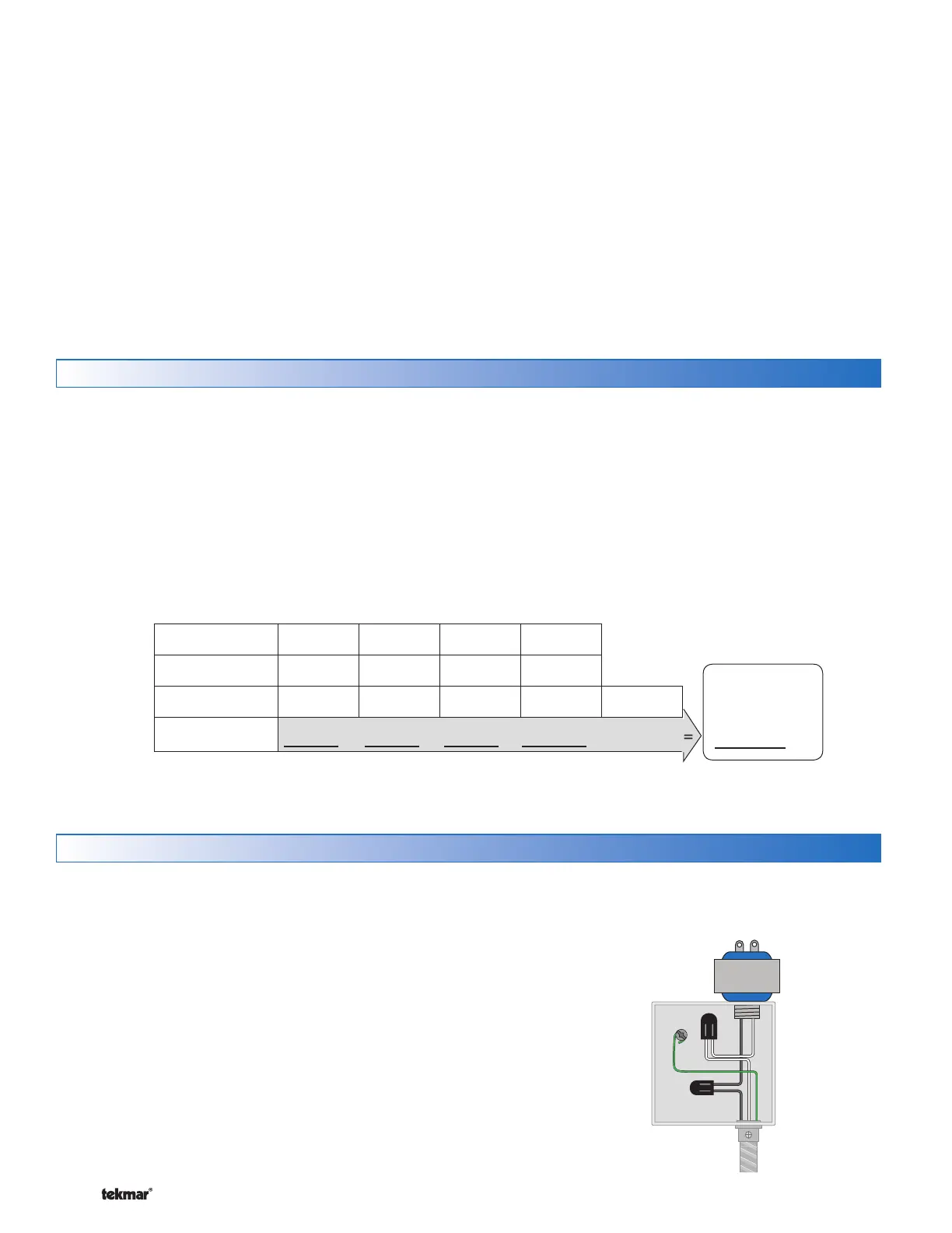
Wire the Ground
Connect the power supply ground to the electrical box
as shown in Figure 1.
Wire the Neutral (N)
Connect the 115 V (ac) neutral (N) wire to the 115 V
(ac) side of the transformer. Use a wire nut or approved
connector. See Figure 1.
Wire the Power (L)
Connect the 115 V (ac) line voltage (L) wire to the 115 V
(ac) side of the transformer. Use a wire nut or approved
connector. See Figure 1.
•
•
•
CAUTION: TURN ALL POWER OFF BEFORE PERFORMING ANY WIRING.
Each cable must be pulled from the equipment to the
control’s plastic enclosure. All low voltage wiring connections
enter the enclosure through conduit knockouts on the
sides, or through the square knockouts on the rear. It is
recommended to label each cable for easy identification.
All low voltage wires are to be stripped to a length of 3/8”
(9 mm) to ensure proper connection to the control.
Pull two conductor 18 AWG LVT cable, up to 500 feet
(150 m) for the following equipment:
tekmarNet
®
2 Thermostats
tekmarNet
®
2 House Control (if applicable)
•
•
24 V (ac) Power
Zone Valves
Boiler T-T (If using End Switch)
Pull three conductor 18 AWG LVT cable for the following
equipment:
tekmarNet
®
4 Accessories (User Switch, Timer)
•
•
•
•
Low Voltage Wiring
-----------------------------------------------------------------------------------
-----------------------------------------------------------------------------------
Power Source
(L, N, Ground)
Figure 1 - Connect
Line Voltage Wires