© 2009 D 263 - 03/09 20 of 36
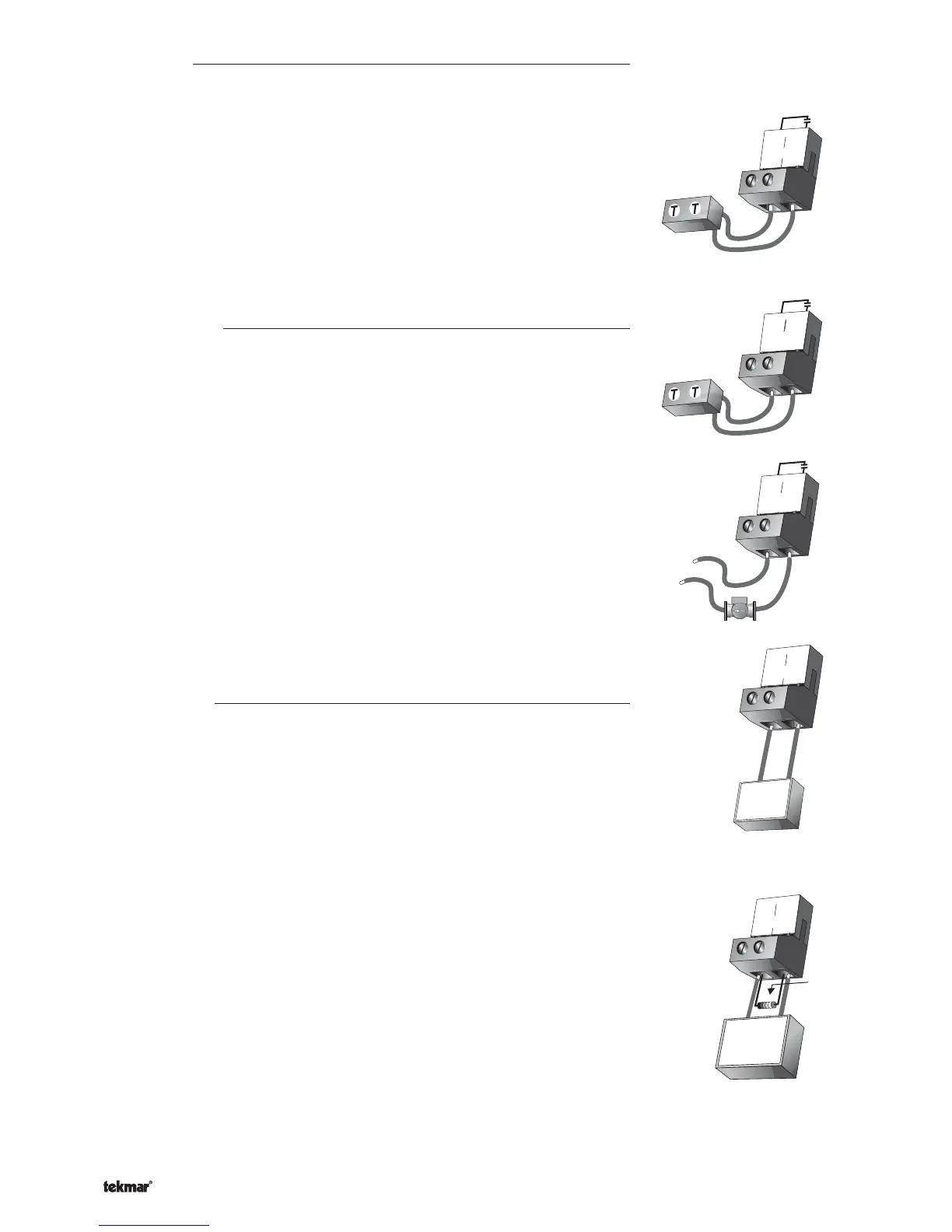
Relay 1 Contact
Mode 1 - Two ON / OFF Stages
The Relay 1 terminals (11 and 12) are isolated outputs in the control. There is no
power available on these terminals from the control. These terminals are to be used
as a switch to either make or break power to a boiler or a Lo fire stage on a single
boiler. Since this is an isolated contact, it may switch a voltage between 24 V (ac) and
230 V (ac).
Mode 2 - One Modulating Boiler and Pump
The Relay 1 terminals (11 and 12) are isolated outputs in the control. There is no
power available on these terminals from the control. These terminals are to be used as
a switch to enable the modulating boiler to operate at Lo fire. Since this is an isolated
contact, it may switch a voltage between 24 V (ac) and 230 V (ac).
Relay 2 / P2 Contact
Mode 1 - Two ON / OFF Stages
The Relay 2 / P2 terminals (13 and 14) are isolated output in the control. There is no
power available on these terminals from the control. These terminals are to be used
as a switch to either make or break power to a boiler or a Hi fire stage on a single
boiler. Since this is an isolated contact, it may switch a voltage between 24 V (ac) and
230 V (ac).
Mode 2 - One Modulating Boiler and Pump
The Relay 2 / P2 terminals (13 and 14) are isolated output in the control. There is no
power available on these terminals from the control. These terminals are to be used
as a switch to either make or break power to a boiler pump. Since this is an isolated
contact, it may switch a voltage between 24 V (ac) and 230 V (ac).
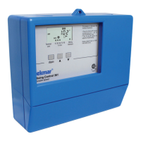
Modulation Output
The Modulation Output Mod 1 terminals (15 and 16) provide a 4 to 20 mA or a 0 to 20 mA
output to the boiler. The modulating outputs replace any mechanical operator such as a
T991. Observe polarity when connecting the control to the boiler.
The 4 to 20 mA output can be converted to 2 to 10 V (dc) using an external 500 Ω resistor
across the Modulation Output terminals (15 and 16).
The 4 to 20 mA output can be converted to 1 to 5 V (dc) using an external 250 Ω resistor
across the Modulation Output terminals (15 and 16).
Relay
12
11
1
1
Relay
14
13
2 / P2
14
13
115 V (ac)
L
N
Relay
2 / P2
Connection to Operate
a 4 - 20 mA Device
15
+
16
–
Mod 1 mA
+
–
4-20 mA
Actuating M
ot
or
6
+
7
–
Mod 1 mA
500 Ω resistor
4 - 20 mA converted
to 2 - 10 V (dc) output
OR
250 Ω resistor
4 - 20 mA converted
to 1 - 5 V (dc) output
Converting the 4 - 20 mA
Output to Operate a
1 - 5 or 2 - 10 V
dc
Device
+
–
1-5 or 2-10 V (dc)
Actuating Motor