6
OR
Sensor and unpowered input connections
Power should never be applied to these terminals. Damage to the
control will result.
Connect the two wires from the Outdoor Sensor 070 to terminals
Com Sen — Out Sen
(18 and 20).
Connect the two wires from the Supply Sensor 071 to terminals
Com Sen — Sup Sen
(18 and 19).
Option: Boiler Return temperature sensor: (Ordered separately)
Connect the two wires from the Universal Sensor 071 to terminals
Com Sen — Ret Sen
(12 and 13).
Option: Indoor temperature feedback sensor.
(One option only)
(1) Connect the two wires from the Indoor Sensor 074 or the tekmar
10K Zone Control to terminals
Com Sen — 10K Sen
(15 and 16).
OR
(2) Connect the two wires from the tekmar 2K RTU
to terminals
Com Sen — 2K RTU
(15 and 17).
Option: Occupied/Unoccupied switch input.
Connect the two wires from the Occupied/Unoccupied dry contact
switch (timer, relay, etc.) to terminals
UnO Sen — Com Sen
(14 and 15).
UnO
Sw
Com
Sen
18 19 20
Com
Sen
10K
Sen
2K
RTU
Sup
Sen
Out
Sen
Com
Sen
Ret
Sen
12 13
14
15 16 17
Do not apply power here!
Maximum 24 Volts
• Connect the power supply for the actuating motor to terminal
Com Mix
(7).
If a tekmar Actuating motor 010 is used
, a 24Vac 12VA power supply for the
control is adequate for operating the motor. Install a jumper wire between
terminal
Power R
(4) and
Com Mix
(7).
• Connect the wire from the OPEN circuit of the actuating motor to the terminal
Opn Mix
(8) of the control. This terminal leads to a 10 amp relay contact
which closes to bring power from terminal
Com Mix
(7) to open the valve.
• Connect the wire from the CLOSE terminal of the actuating motor to the terminal
Cls Mix
(9) of the control. This terminal leads to a 10 amp relay contact which
closes to bring power from terminal
Com Mix
(7) to close the valve.
3
5
4
6
CR
10 11
Boiler
789
Com
Mix
Opn
Mix
Cls
Mix
Pump
Power
Power supply
connection to tekmar
Actuating Motor 010
Output
to Motor
Maximum 24 Volts
Powered input connections
If a 24Vac external heat demand signal is used, (zone valve end switches, etc.) connect the
wiring from the Heat Demand circuit to terminals
Heat Dem — Heat Dem
(1 and 2). When
24Vac is applied to these terminals, the control will respond to a "call for heat" from the system.
UnO
Sw
Com
Sen
18 19 20
Com
Sen
10K
Sen
2K
RTU
Sup
Sen
Out
Sen
Com
Sen
Ret
Sen
12 13
14
15 16 17
12
Dem
Dem
Heat
UnO
Sw
Com
Sen
18 19 20
Com
Sen
10K
Sen
2K
RTU
Sup
Sen
Out
Sen
Com
Sen
Ret
Sen
12 13
14
15 16 17
UnO
Sw
Com
Sen
18 19 20
Com
Sen
10K
Sen
2K
RTU
Sup
Sen
Out
Sen
Com
Sen
Ret
Sen
12 13
14
15 16 17
UnO
Sw
Com
Sen
18 19 20
Com
Sen
10K
Sen
2K
RTU
Sup
Sen
Out
Sen
Com
Sen
Ret
Sen
12 13
14
15 16 17
UnO
Sw
Com
Sen
18 19 20
Com
Sen
10K
Sen
2K
RTU
Sup
Sen
Out
Sen
Com
Sen
Ret
Sen
12 13
14
15 16 17
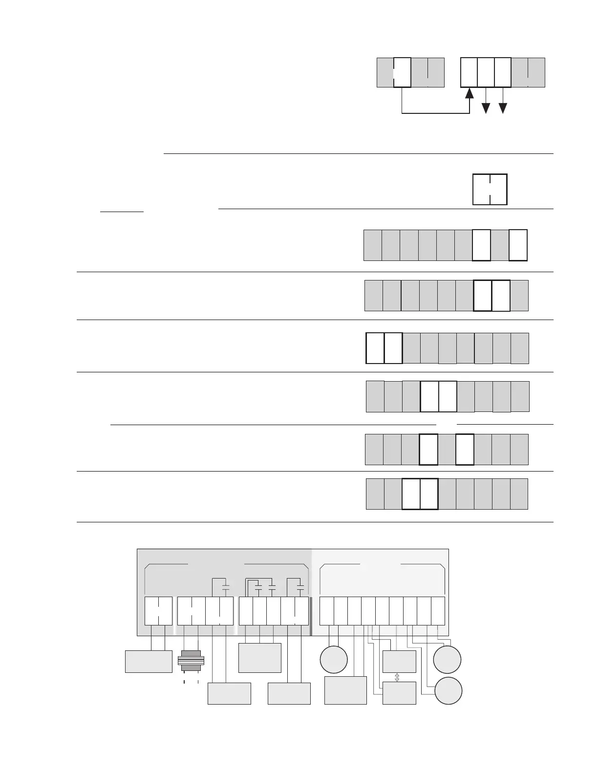
Note: This is not a wiring diagram.
For a detailed wiring schematic of your specific application, refer to the Application Brochure A 354.
type 354
Do not apply
power here!
Maximum 24 Volts
10A
10A
Safety Divider
24
Vac
External
24Vac
60Hz class II
transformer
OR
Outdoor
Sensor
070
Supply
Sensor
071
12 13 14 15
UnO
Sw
Com
Sen
10K
Sen
2K
RTU
Com
Sen
16
Sup
Sen
17
Out
Sen
89107
Com
Mix
Opn
Mix
Cls
Mix
12
Dem
Dem
4563
CR
11
18
19 20
Com
Sen
Ret
Sen
10A 10A
Boiler
Unoccupied
Switch (optional)
to switch control to
Unoccupied mode
or Timer 030
Return
Sensor 071
(optional)
2K RTU
(optional)
10K Indoor
Sensor or
Zone Control
(optional)
Heat Demand
Deliver 24Vac signal
when heat requested
from system
120/240Vac
Boiler Relay
closes to turn
on boiler
Actuating Motor
Relay
Closes to operate
Mixing Valve motor
(refer to A-354 for
wiring)
Pump Relay
closes to turn on
System Pump
Pump
Heat Power
Electrical connections to the terminal plugs of the type 354 control. Control relays are shown in "power down" condition.
 Loading...