Do you have a question about the Tekmar Mixing Control 356 and is the answer not in the manual?
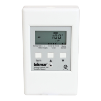
Description of the control's LCD display and button functions for setup and monitoring.
Explanation of the various fields and components of the control's LCD display.
Defines the meaning of symbols and pointers shown on the control's display.
Overview of control functions, powering up, and general operating modes.
Details on mixing control strategies, including outdoor reset and setpoint operation.
Information regarding boiler control, minimum temperature settings, and sensor placement.
Instructions for initial wiring connections of sensors and pump before control mounting.
Procedures for testing sensors and power supply connections using a multimeter.
Detailed steps for connecting power, mixing demand, boiler, and pump circuits.
Wiring instructions for outdoor, boiler, and mixing sensors to the control.
Configuration options using the Advanced/Installer DIP switch.
Step-by-step guide to configure the control for outdoor reset operation.
Step-by-step guide to configure the control for fixed setpoint operation.
Displays current system status, outdoor air, mixed supply, and boiler temperatures.
Details of adjustable parameters like ROOM, MIX TARGET, OUTDR DSGN, and Terminal Unit.
A systematic approach to diagnosing and resolving heating system problems.
Lists and explains common error codes displayed by the control and their causes.
Information on warranty terms, coverage, and the procedure for returning products.
| Brand | Tekmar |
|---|---|
| Model | Mixing Control 356 |
| Category | Controller |
| Language | English |