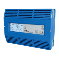
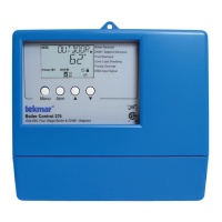
What does NO HEAT ALERT mean on my Tekmar Controller?
- NNicole ReeseSep 23, 2025
If your Tekmar Controller displays a 'NO HEAT ALERT', it means there has been no change in supply temperature within the specified period of time.
What does NO HEAT ALERT mean on my Tekmar Controller?
If your Tekmar Controller displays a 'NO HEAT ALERT', it means there has been no change in supply temperature within the specified period of time.
What to do if my Tekmar 284 shows a BOILER SUPPLY SENSOR ERROR?
If your Tekmar Controller displays a 'BOILER SUPPLY SENSOR ERROR', it means the control couldn't read the boiler supply sensor due to an open or short circuit. To resolve this, check the boiler supply sensor and its wiring.
What to do if my Tekmar 284 Controller shows a BOILER RETURN SENSOR ERROR?
If your Tekmar Controller displays a 'BOILER RETURN SENSOR ERROR', it means the control couldn't read the boiler return sensor due to an open or short circuit. To resolve this, check the boiler return sensor and its wiring.
What to do if my Tekmar 284 displays a DHW SENSOR ERROR?
If your Tekmar Controller displays a 'DHW SENSOR ERROR', it means the control couldn't read the DHW sensor because of an open or short circuit. To fix this, check the DHW sensor and its wiring.
What to do if my Tekmar Controller shows an OUTDOOR SENSOR ERROR?
If your Tekmar Controller displays an 'OUTDOOR SENSOR ERROR', the control was unable to read the outdoor sensor due to an open or short circuit. You should check the outdoor sensor and its wiring.
What does BOILER (#) OUTLET SENSOR MAXIMUM EXCEEDED mean on my Tekmar Controller?
If the Tekmar Controller shows 'BOILER (#) OUTLET SENSOR MAXIMUM EXCEEDED', the boiler (#) outlet temperature exceeds the maximum output setting.
What does 'tekmarNet® DUPLICATE SCHEDULE MASTER ERROR' mean on my Tekmar 284 Controller?
If your Tekmar Controller displays 'tekmarNet® DUPLICATE SCHEDULE MASTER ERROR', it indicates a duplicate master schedule was detected on the TN4 BUS.
What to do if my Tekmar 284 displays tekmarNet® SCHEDULE MEMBER ERROR?
If your Tekmar Controller displays 'tekmarNet® SCHEDULE MEMBER ERROR', check the schedule master wiring and the schedule master address on the TN4 BUS.
What to do if my Tekmar Controller displays FLOW PROOF CALL ERROR?
If your Tekmar Controller displays a 'FLOW PROOF CALL ERROR', you should check the flow proving device and its wiring.
What to do if my Tekmar 284 Controller displays PRIMARY PUMP P2 FLOW PROOF FAILURE?
If your Tekmar Controller displays 'PRIMARY PUMP P2 FLOW PROOF FAILURE', you should check the flow proving device and its wiring.
Configures individual boiler settings for optimal plant flexibility.
Selects the primary operating mode for the heating system.
Sets the lowest allowable target temperature for the boiler.
Determines target water temperature based on outdoor air temperature.
Enables or disables setpoint heating operation for various loads.
Describes methods to request indirect domestic hot water.
Selects between Modbus® and BACnet® IP communication protocols.
Explains primary pump sequencing, stand-by operation, and logging.
Proves flow after pump activation to ensure proper operation.
Details how to connect the 115V AC input power to the control.
Explains wiring for boiler pumps and isolation valves.
Guides on mounting the outdoor sensor for accurate temperature readings.
Explains how to wire boiler outlet sensors for temperature monitoring.
Describes how to connect an Energy Management System to the control.
Explains how to use the HAND mode for manual operation and testing.
Manages access levels for different users to menus and settings.
Configures key features like flow proof and schedule operation via DIP switches.
Describes the different fields and components of the control's display.
Selects the main operating mode: RSET, SETP, DDHW, EMS, or BAS.
Defines the minimum allowed boiler target temperature for non-condensing groups.
Selects whether a specific boiler is operational or disabled.
Selects boiler operation type: modulating, single-stage, two-stage, or EMS.
Records the total running time of the boiler since the last clear.
Records the total running time of primary pump 1 since last cleared.
Lists common error messages and their potential causes and solutions.
Lists additional error messages and troubleshooting tips.
Lists remaining error messages and troubleshooting guidance.
Outlines the terms and conditions of the product warranty and return process.
| Category | Controller |
|---|---|
| Application | Hydronic heating systems |
| Zones Supported | Up to 4 |
| Power Supply | 24 VAC |
| Output | Relay |
| Mounting | Wall mount |
| Control Method | On/Off |
| Display | LED |
| Input Voltage | 24 VAC |
| Output Voltage | 24 VAC |
Loading...