© 2016 284_D - 05/16
29 of 60
A Watts Water Technologies Company
5V
dc
Out
Pressure
In
+
14
Vdc
-
15
Gnd
13
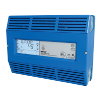
Wiring a Pressure Sensor Terminals 13 to 15
An analog pressure sensor can be connected to the 284 to provide water pressure monitoring. The
control supports a V (dc) style pressure sensor with a signal range of 0.5 to 4.5 V (dc). Examples
of compatible aftermarket pressure sensors include the Honeywell PX2 (AA) series and the
Measurement Specialties 7100 series.
•
Connect one wire from the power supply (+5 VDC) on the pressure sensor to the 5V dc Out
terminal 13.
• Connect one wire from the pressure signal on the pressure sensor to the Vdc (+) In terminal 14.
• Connect one wire from the GND (0V) on the pressure sensor to the Gnd (-) terminal 15.
Boil
In
Vent
23 24 25
Com
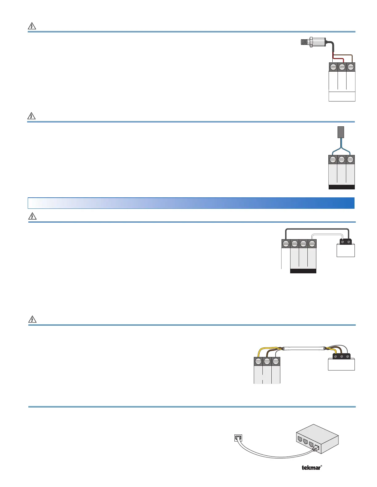
Wiring a Vent Sensor Terminals 23, 25
A vent sensor can be connected to the 284 to provide monitoring of the common boiler plant exhaust vent temperature.
Compatible sensors include a 10K ohm NTC curve J thermistor.
The control is capable of displaying temperatures up
to 500°F (260°C).
The vent sensor can also be used to provide a vent temperature limiting feature.
• Connect one wire from the vent sensor to the Vent terminal 23.
• Connect the second wire to the Com terminal 25.
+
-
EMS
Com
Out
17
Boil
Sup
18
-
19
In
EMS
+
16
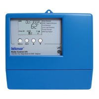
EMS Connection Terminals 16, 19
Modbus
®
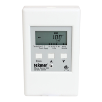
Connection Terminals 40 to 42
BACnet
®
Connection RJ45 Plug
A Building Automation System (BAS) can be connected to the 284 for remote
monitoring & adjustment capability. BACnet
®
IP communications use an
ethernet socket. Use a CAT-5E or CAT-6 cable. The maximum recommended
cable length for CAT-5E is
150 ft. (45.7 m)
&
300 ft. (91.4 m)
for CAT-6.
•
Connect the Ethernet RJ45 socket on the BACnet
®
IP network to the
Ethernet RJ45 socket on the 284.
A Building Automation System (BAS) can be connected to the 284 for remote monitoring
& adjustment capability. Modbus
®
communications use an RS 485 connection. Use
18 AWG Twisted Shielded Pair cable. Cable length is dependent on the baud rate &
whether or not terminating resistors are used. Refer to the BAS Integration Manual
284_B for details on the maximum recommended cable length.
• Connect the B (+) terminal on the BAS network to the RS 485 B (+) terminal 40.
• Connect the A (-) terminal on the BAS network to the RS 485 A (-) terminal 41.
• Connect the ground (G) terminal on the BAS network to the Gnd terminal 42.
An Energy Management System (EMS) can be connected to the 284 to provide a target water
temperature. Either a 0 to 10 V (dc) or 2 to 10 V (dc) signal may be used.
• Connect one wire from the EMS to the EMS (+) In terminal 16.
• Connect a second wire from the EMS to the Com (-) terminal 19.
A 0 - 20 mA signal can be converted to a 0 - 10 V (dc) signal by installing a 500 Ω resistor in
parallel between the Com (-) & EMS (+) In terminals (19 & 16). The EMS Signal setting must
be set to 0-10.
BACnet
Network
Switch
Boiler
Control 284
EMS, Modbus
®
& BACnet
®
Connections
BAG
Master
40 41 42
Gnd
+–
RS 485
BA
(+)
(-)
A 4 - 20 mA signal can be converted to a 2 - 10 V (dc) signal by installing a 500 Ω resistor in parallel between the Com (-) &
EMS (+) In terminals (19 & 16). The EMS Signal setting must be set to 2-10.
The APP MODE setting in the Setup Menu must be set to EMS.