© 2016 284_D - 05/16
2 of 60
A Watts Water Technologies Company
Table of Contents
Sequence of Operation .....................................................2
Boiler Setup ................................................................... 2
System Setup ................................................................ 5
Boiler Plant Operation ................................................... 7
Outdoor Temperature Reset Operation ...................... 10
Setpoint Operation ...................................................... 12
Energy Management System (EMS) Operation .......... 13
Indirect Domestic Hot Water (IDHW) Operation ..........14
Dedicated Domestic Hot Water (DDHW) Operation ....17
Building Automation System (BAS) Operation .............17
Pump Operation .......................................................... 18
C.A. Damper & DHW Recirculation ............................. 20
Setting the Schedule ................................................... 20
Time Clock ................................................................... 21
tekmarNet
®
4 Communication ...................................... 21
Installation .......................................................................22
Installation Location ..................................................... 22
Control Wiring .............................................................. 23
Sensor Installation & Wiring ........................................ 26
EMS, Modbus
®
& BACnet
®
Connections..................... 29
Wiring the tekmarNet
®
Devices ................................... 30
Testing the Sensor Wiring ........................................... 30
Testing the Control Wiring ............................................... 31
Control Settings ...............................................................33
Access Level ............................................................... 33
DIP Switch Settings ..................................................... 33
User Interface ..................................................................34
Display & Symbols ....................................................... 34
Navigating the Display ................................................. 35
View Menu .................................................................. 35
Setup Menu ................................................................ 37
Source # Menu ............................................................ 43
BAS Menu .................................................................... 45
Monitor # Menu ............................................................ 47
Monitor Menu .............................................................. 48
Time Menu ................................................................. 50
Schedule Menu ........................................................... 51
Toolbox Menu ............................................................. 52
Manual Override ......................................................... 54
Troubleshooting ...............................................................56
Error Messages .......................................................... 56
Technical Data ............................................................60
Limited Warranty & Product Return Procedure ...............60
Sequence of Operation
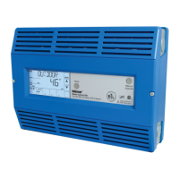
The 284 is able to operate up to four boilers as a heat source.
Each boiler is independently configured allowing for maximum
plant flexibility.
Boiler Enable
-------------------------------------
This setting selects whether the boiler is operational or not.
OFF
The boiler is disabled & will not be included in the plant
operation.
AUTO
The boiler is enabled & will be included in the plant
operation.
Copy Boiler 1
-------------------------------------
Many boiler installations will have multiple identical boilers.
To reduce the number of settings required, certain settings
of boiler 1 are copied to boiler 2 by setting the Boiler 2 Copy
setting to Boil1. Copy settings are also available for boiler 3
& boiler 4.
OFF
The settings from boiler 1 are not copied. This allows for
individual boiler settings.
Boil 1
The settings from boiler 1 are copied.
Condensing
--------------------------------------
This setting selects whether the boiler is condensing or non-
condensing & defines what boiler group it is part of.
NO
The boiler is non-condensing & is part of the non-condensing
boiler group.
YES
The boiler is condensing & is part of the condensing boiler group.
Boiler Type
---------------------------------------
The 284 has four different boiler types to choose from. Use
the Boil TYPE setting to select one of the following:
MOD
The modulating output operates a modulating boiler by controlling
the burner firing rate. The Stage 1 relay is also used to give
a boiler enable to allow the modulating boiler to go through
ignition sequence. The Stage 1 relay may not be required on
all modulating boilers.
1STG
The Stage 1 relay operates a single, stage boiler by cycling
the burner stage on & off.
2STG
The Stage 1 & Stage 2 relays operate a single, two stage boiler
by cycling the burner stages on & off.
EMS
The modulating output operates a boiler that interprets an
analog input signal as a target temperature. The temperature
rails (minimum and maximum) are adjustable between 50°F
(10.0°C) & 210°F (99.0°C).
• VDC SIGN MIN
Sets the minimum analog Vdc signal which corresponds to
the minimum temperature (EMS TEMP MIN).
• EMS TEMP MIN
Sets the temperature on the low end which corresponds to the
minimum analog signal (Vdc Min / 4 mA).
• EMS TEMP MAX
Sets the temperature on the high end which corresponds to
the maximum analog signal (10 Vdc / 20 mA).
Boiler (Source (#) Menu) Setup & Operation