© 2016 284_D - 05/16
26 of 60
A Watts Water Technologies Company
Mounting the Outdoor Sensor
--------------------------------------------------------------------------
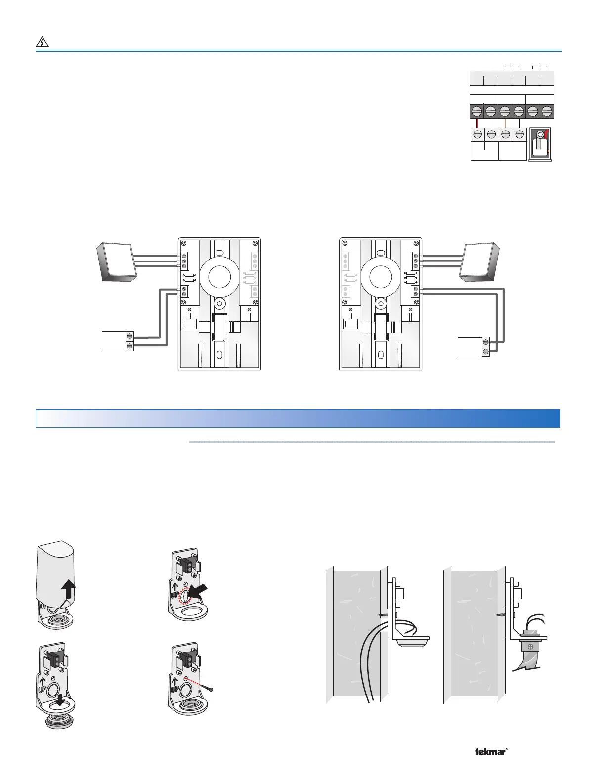
Sensor Installation & Wiring
Mod Enable
TT+
-
51 52
Mod
Boiler 1
53 54
Stage 1Stage 2
55 56
+
-
Modulating Boiler Wiring Terminals 51 to 72
For modulating boilers that do not require an enable:
• The 284 provides either a 4-20 mA or a 0-10 V (dc) output to each boiler.
• Polarity is important.
•
Connect the Mod + terminals from boilers 1, 2, 3 and 4 to the 284 terminals 51, 57, 63 and 69,
respectively.
•
Connect the Mod - terminals from boilers 1, 2, 3 and 4 to the 284 terminals 52, 58, 64 and 70,
respectively.
Some modulating boilers may also require an on / off signal in addition to the modulating
signal. See the Stage 1 terminals for boilers 1, 2, 3 and 4.
Modutrol IV
tekmar
B
R
W
+
-
tekmar
V9055
+
-
B
R
W
0 - 135 Ω
Actuating
Motor
B
R
W
Mod
+
-
Modutrol IV
tekmar
B
R
W
+
-
tekmar
V9055
+
-
B
R
W
B
R
W
V9055™
0 - 135
Ω
Motor
Mod
+
-
The 4 to 20 mA output can be converted to a 0 - 135 Ω output
for a Modutrol IV™ gas valve actuating motor using a 0 - 135 Ω
tekmar Converter 005 (sold separately).
The 4 to 20 mA output can be converted to a 0 - 135 Ω output
for a V9055™ gas valve actuating motor using a 0 - 135 Ω
tekmar Converter 005 (sold separately).
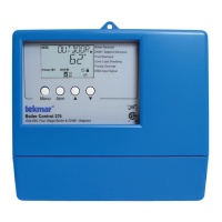
Boiler
Control
284
Boiler
Control
284
Modutrol IV™ and V9055™ are trademarks of Honeywell, Inc.
Remove
cover by
sliding
upwards
away from
the base.
To wire from
the back,
remove the
knock-out in
the sensor
base.
S1
S1
If using
conduit,
remove
the flexible
plug from
the base
bottom.
S1
S1
Attach the
base to
the wall,
soffit or
electrical
box.
S1
S1
•
The 070 can be mounted directly onto a wall with the wiring
entering through the back or bottom of the enclosure. Do
not mount the 070 with the conduit knockout facing upwards
as rain could enter the enclosure and damage the sensor.
• In order to prevent heat transmitted through the wall from
affecting the sensor reading, it may be necessary to install
an insulating barrier behind the enclosure.
•
The 070 should be mounted on a wall which best represents
the heat load on the building (a northern wall for most
buildings and a southern facing wall for buildings with large
south facing glass areas). The 070 should not be exposed
to heat sources such as ventilation or window openings.
•
The 070 should be installed at an elevation above the ground
that will prevent accidental damage or tampering.