Step Four Electrical connection to the control
Power and output connections
The installer should test to confirm that no voltage is present at any of the wires.
• Install the control into the base, sliding it down until it snaps into place.
• All electrical connections are made directly to the plug terminals.
• Connect the 24Vac power supply from the secondary side of a 24Vac class II transformer to
terminals
Power C — Power R
(3 and 4).
Do not connect either of the transformer terminals
to ground.
• Connect the Pump circuit to terminals
Pump
(5 and 6). These terminals lead to a 10 amp dry relay
contact which closes when the control requires pump operation.
Note:
The type 354 is approved for low voltage only (Maximum 24Vac). The pump should
be
switched through an isolation relay approved for the line voltages required to operate the pump.
• Connect the boiler circuit to terminals
Boiler
(10 and 11). These terminals lead to a 10 amp
dry relay contact which closes when the control requires boiler operation. Boilers with a 24Vac
control circuit can be switched directly through the control. If higher voltages are used, an
isolation relay should be added.
Caution
Improper installation and operation of this control could result in damage to equipment and possibly even personal injury.
It is your responsibility to ensure that this control is safely installed according to all applicable codes and standards.
Step One Getting ready
Check the contents of this package. If any of the contents listed are missing or damaged, please refer to the Limited Warranty
and Product Return Procedure on the back of this brochure and contact your wholesaler or tekmar sales agent for assistance.
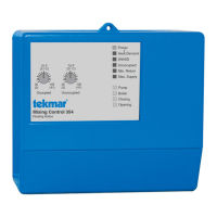
Type 354 includes:
• One Control 354 • One Outdoor Sensor 070 • One Supply Sensor 071
• One Data Brochure D 354 • One Data Brochure D 001 • Application Brochures A 354
Other information available:
• Essay E 001 • Essay E 002
Read brochures A 354 and select the correct Application for your job.
Note:
Carefully read the details of the Application, and the Sequence of Operation sections in all applicable brochures to ensure that you
have chosen the proper control and understand its functions within the operational requirements of your system. Some applications
feature boiler return protection and require ordering an additional Universal Sensor 071.
Step Two
Mounting of the base
The control should be removed from its base by pressing down on the release clip in the wiring chamber and sliding upwards
on the control. The base is then mounted in accordance with the instructions in the Data Brochure D 001.
Step Three
Rough-in Wiring
All electrical wiring terminates in the control base wiring chamber. It has standard 7/8" (22mm) knock-outs that will accept
common wiring hardware and conduit fittings. Before breaking out the knock-outs, check the wiring diagram and select those
sections of the chamber with common voltages, since the safety dividers will later prevent wiring from crossing between sections.
Power should not be applied to any of the wires during this rough-in wiring stage.
• Install the Outdoor Sensor 070, and the Supply Sensor 071 according to the instructions in the Data Brochure D 001 and
run the wiring back to the control.
Option:
A Universal Sensor 071 can be installed to provide Minimum Boiler Return protection. See Brochures A 354.
Option:
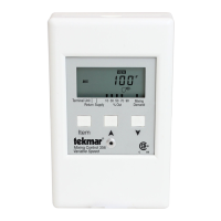
An Indoor Sensor 074, RTU or Zone control can also be connected. See individual sensor instructions.
• Install the wiring from the other system components (Boiler, Pump, Actuating Motor, Heat Demand circuit) to the base.
• Install a 24Vac Class II transformer with a minimum 12VA rating close to the control, and run the wiring from the transformer
to the base.
A Class II transformer must be used. Do not connect any of the transformer terminals to ground, as damage to
the control may result.
5
34
6
CR
Power
5
Pump
Installation
Maximum 24 Volts
56
Pump
34
CR
Power
10 11
Boiler
789
Com
Mix
Opn
Mix
Cls
Mix
 Loading...