ClearLink Hardware Manual / Rev. 1.00 7
T
EKNIC, INC. PHONE (585)784-7454
Parts Overview
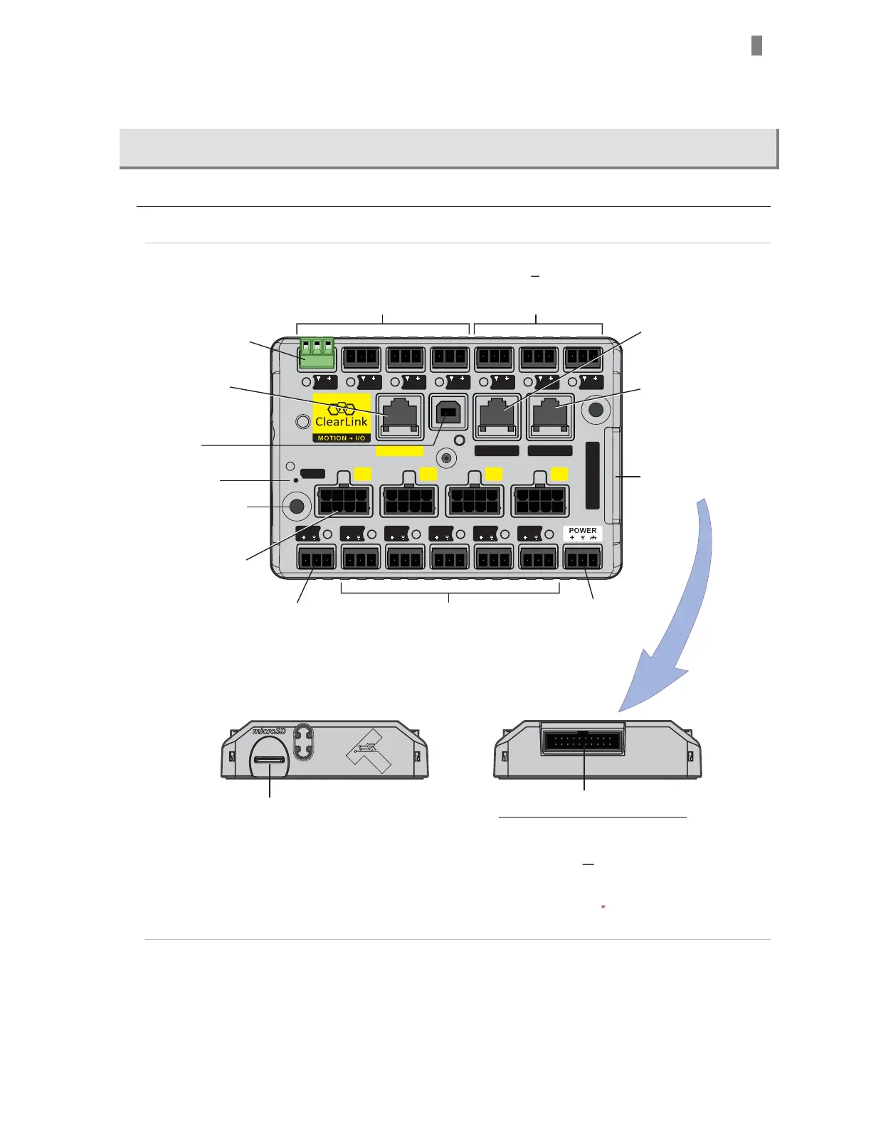
Parts of a ClearLink
EtherNet/IP
M-2 M-3M-1M-0
ClearLink
A-12 A-11 A-10 A-9 DI-8 DI-7 DI-6
5V COM-0 CCIO Port
COMBINED I/O
I/O-5I/O-4I/O-3I/O-2I/O-0 I/O-1
RESET
Dedicated plug-in
terminal blocks for
each I/O point
Digital Inputs or
0-10V Analog Inputs (4x)
Digital Inputs (3x)
or
Differential Encoder Input (3-channel)
Teknic Encoder Board PN
CL-ENCDR-DFIN *** required.
Card Slot
(not used for ClearLink)
Combined I/O Header
Can be used in only one of the two ways listed
EtherNet/IP Port
USB Port
(not used)
Mounting Holes (2x)
*Digital outputs I/O-0 through I/O-3 have
built-in clamping circuitry and are capable of
driving coils of up to 9-watts max.
I/O-4 , I/O-5 can drive up to 18 watts max.
Reset Switch
Motor Connectors
(4x) M0-M3 Control
ClearPath motors,
step motor drives, or
servo motor drives
Digital Input,
Digital Output*, or
Analog Output
(4-20mA or 0-20mA)
Combined I/O Header
see description below
Communication Port
RJ-45 connector, compatible
with UART, or RS-232 devices
DC Power Input
24VDC
Digital Inputs or
Digital Outputs*
CCIO Port
RJ-45 connector, used to
connect CCIO-8 I/O
expansion module(s)
Breaks out all 13 I/O points.
(Provides an alternative
hookup path to the individual
3-pin I/O connectors.)
Connect optional Teknic Differential
Encoder Board here
(Teknic PN CL-ENCDR-DFIN***).
If Encoder Board is used, DI-6,7,8
3-position connectors cannot be
used and must remain unpopulated.
or
ENCODER BOAR
VAILABLE
N.
**
ClearLink top and side views
 Loading...