16
1737·08
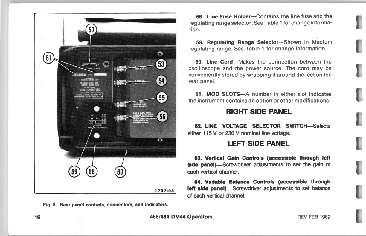
Fig.
8.
Rear panel controls,
connectors,
and indicators.
58. Line Fuse
Holder-Contains
the line fuse and the
regulating range selector. See Table
1
for
change
informa-
tion.
59. Regulating Range
Selector-Shown
in Medium
regulating range. See Table 1
for
change information.
60.
Line
Cord-Makes
the
connection
between the
oscilloscope and the power source. The cord may
be
conveniently stored by
wrapping
it around the feet on the
rear panel.
61
.
MOD
SLOTS-A
number
in either slot indicates
the instrument contains an
option
or
other modifications.
RIGHT SIDE PANEL
62. LINE VOLTAGE SELECTOR
SWITCH-Selects
either 115 V
or
230 V nominal line voltage.
LEFT SIDE PANEL
63. Vertical Gain Controls
(accessible
through
left
side
panel)-Screwdriver
adjustments to set the gain
of
each vertical channel.
64. Variable Balance Controls
(accessible
through
left
side
panel)-Screwdriver
adjustments to set balance
of
each vertical channel.
466/464 DM44 Operators
REV FEB 1982