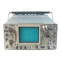
Do you have a question about the Tektronix TAS 465 and is the answer not in the manual?
Explains symbols and terms used in manuals and on equipment for safety information.
Lists precautions to ensure personal safety and prevent equipment damage during operation.
Describes the front-panel controls, knobs, and on-screen menus for operating the oscilloscope.
Details the trigger system features for configuring triggers by source, slope, and mode.
Lists nominal traits related to the vertical deflection system of the oscilloscope.
Lists the conditions under which the oscilloscope's electrical characteristics are tested.
Details warranted characteristics for the vertical deflection system.
Lists typical characteristics for the vertical deflection system.
Details the procedure for compensating the oscilloscope probe for accurate measurements.
Provides a visual overview of the oscilloscope's menu structure and functions.
Describes the microprocessor design and its core functions.
Describes the self-tests performed by the oscilloscope on power-on.
Outlines procedures to verify the oscilloscope's functions and performance.
Procedure to check DC gain and voltage measurement accuracy.
Lists the sequence of individual adjustment steps.
Procedure for factory horizontal calibration.
Lists safety precautions before performing any servicing.
Precautions to prevent electrostatic discharge damage.
Important preparation steps before removal/installation.
Procedure to remove the A62 front panel module.
A matrix to help identify modules based on symptoms.
Describes optional warranty and service plans.
Information on how to order replacement parts.
Lists manufacturer codes and their corresponding company information.
Explains the use of component locator diagrams and lookup tables.
Information on how to order mechanical replacement parts.
| Type | Analog Oscilloscope |
|---|---|
| Bandwidth | 100 MHz |
| Channels | 2 |
| Vertical Sensitivity | 2 mV/div to 5 V/div |
| Display | CRT |
| Maximum Sweep Speed | 5 ns/div |
| Input Coupling | AC, DC, GND |
| Sample Rate | N/A (Analog) |
| Memory Depth | N/A (Analog) |
| Input Impedance | 1 MΩ |
| Trigger Modes | Auto, Normal |


 Loading...