$.,-& '- +( .+ ,
+/# '.%
5Ć17
+ + *.#,#- , Low Frequency Output Compensation adjustment proceĆ
dure.
1. Display channel 1, turning all others off.
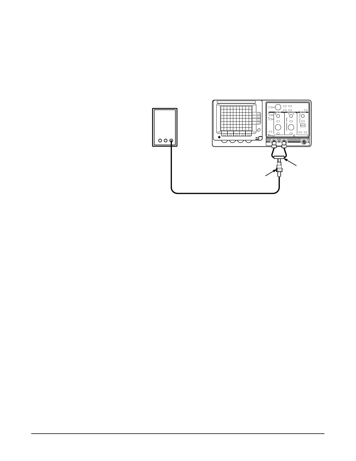
2. Connect the high amplitude output of the pulse generator to the
and inputs as shown in Figure 5Ć13.
50 W Termination
DualĆinput
Coupler
Precision Cable
Pulse Generator
#".+ 10-- '.-(+ (&) ',-#(' ,- -.)
3. Set the pulse generator high amplitude period to 1 ms.
4. Press the button.
5. Press the button and set to .
6. Set the volts/div scale to 200 mV.
7. Set the sec/div scale to 200 ms.
8. Using the vertical control and the generator pulse amplitude,
obtain a 5 division, vertically centered display of channel 1.
9. Set the volts/div scale to 100 mV.
10. Press the button.
11. Press the button and make the following selections
from the menu:
H Set to
H Set to !!
H Set to !!
H Set to .%%
H Set the volts/div scale to 100 mV
H Position the channel 2 display approximately 0.5 divisions below the
channel 1 display
 Loading...

