# " "
" "
2Ć4
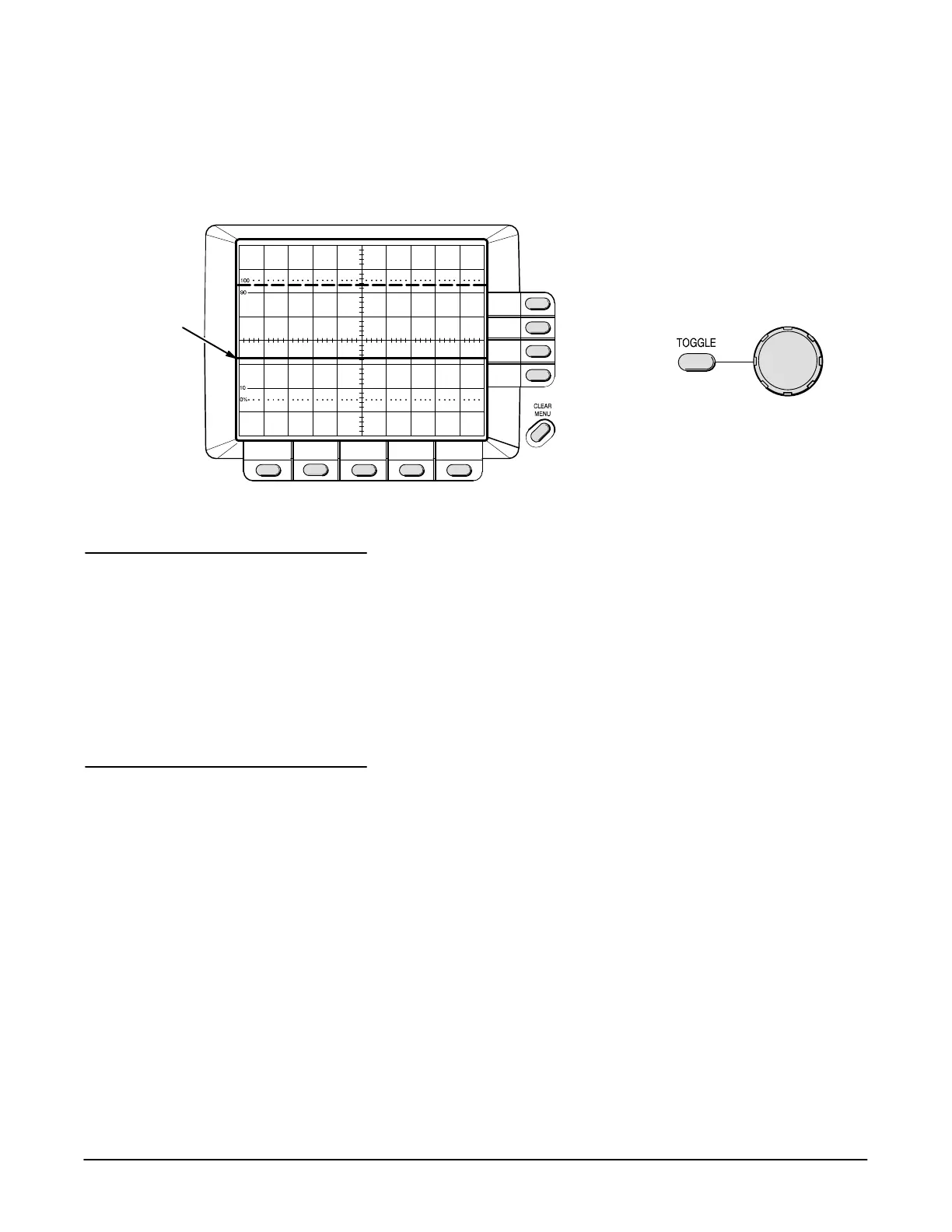
4. Now two horizontal bar cursors are displayed. The active (movable) one
is a solid line and the inactive one is a dashed line. Use the General
Purpose Knob to move the active cursor and use the button to
select which cursor is active.
Position Active
Cursor
Set
Active Cursor
Active Cursor
The TAS 465 Oscilloscope accepts signals through the front panel input
connectors labeled and . The probes you use for taking measureĆ
ments should only be those supplied with the TAS 465 Oscilloscope. ConĆ
necting signals to the TAS 465 Oscilloscope is also possible with the use of
50 W coaxial cables.
Before using any probe to take measurements, compensate the probe to
match the input channel. See Compensating the Probe on page 2Ć5.
The feature of the TAS 465 Oscilloscope automatically sets most
of the front panel controls.
1. Connect the probe compensation signal (from the
connector on the front panel) to either channel of the oscilloscope and
display that channel (see Figure 2Ć5). Turn all other channels off.
2. Press the button on the front panel. Wait one to three secĆ
onds to allow the instrument to adjust all the control settings.
The instrument will trigger on the waveform, display at least one complete
cycle, and center it horizontally on the CRT. The baseline of the waveform
will be at the center horizontal graticule line (see Figure 2Ć4). The intensity
level is increased if set too low for a viewable display.
"
!
 Loading...

