#/$,/* +!# #010
#/3'!# +2 )
4Ć17
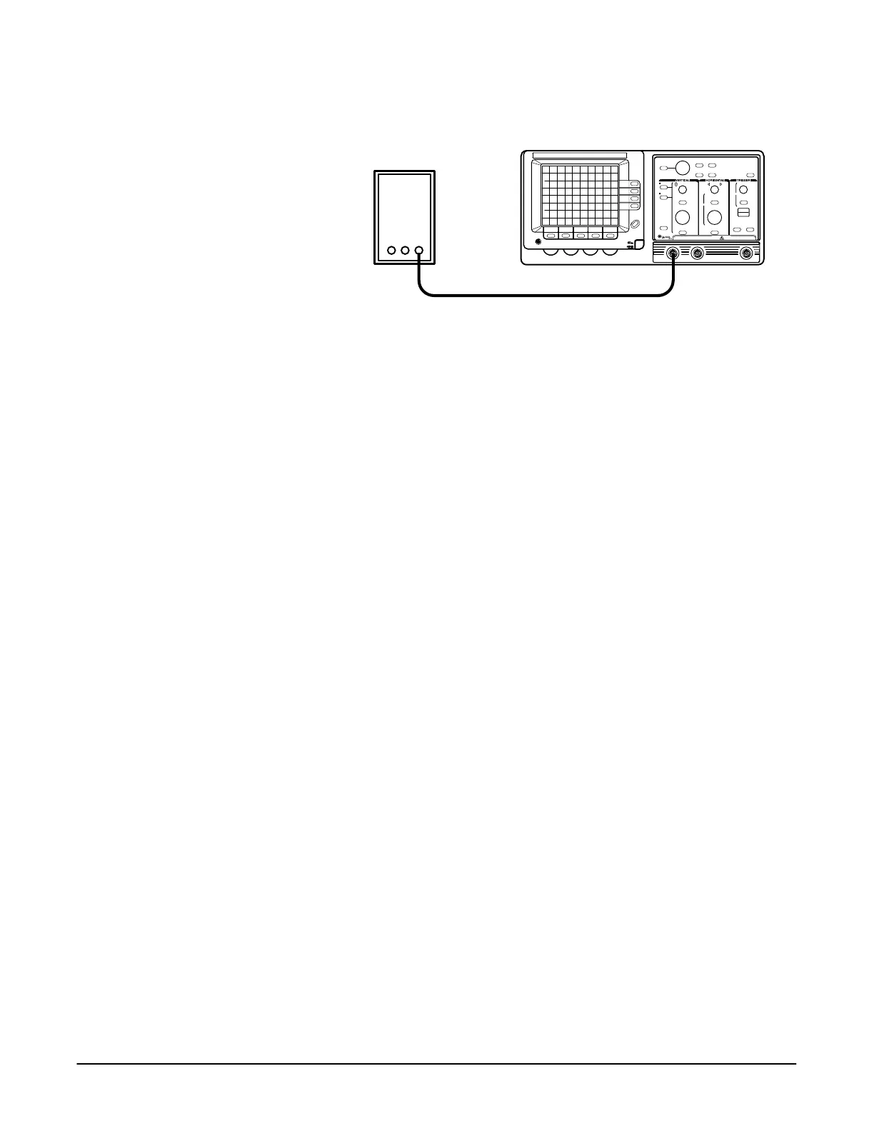
8. Connect the DC calibration generator to the input as shown in
Figure 4Ć7.
DC Calibration Generator
Precision Cable
'%2/# 65/'%%#/ #3#) #01 #12-
9. Set the DC calibration generator for a 200 mV output.
10. Press the button.
11. Check that the Trigger Level Accuracy readout is in the range of 169 mV
to 231 mV.
12. Press the button and set to ))'+%.
13. Press the button.
14. Check that the Trigger Level Accuracy readout is in the range of 169 mV
to 231 mV.
15. Press the button, displaying the delay trigger
menu.
16. Set to 2+0 $1#/ and to &.
17. Press the button.
18. Check that the Trigger Level Accuracy readout is in the range of 169 mV
to 231 mV.
19. Disconnect the test setup from the oscilloscope.
20. Press the button and set to '0'+%.
21. Press the button and set to $$.
&#!( ,2-)'+% +"4'"1&
.2'-*#+1 #.2'/#" One leveled sine wave generator (item 8), one preciĆ
sion coaxial cable (item 5), and one 50 W termination (item 3).
1. Display the channel to be verified, turning all others off.
2. Connect the output of the sine wave generator to the channel to be
verified as shown in Figure 4Ć8.

 Loading...
