!&0./(")/ -* "!0-".
"-1% " )0'
5Ć7
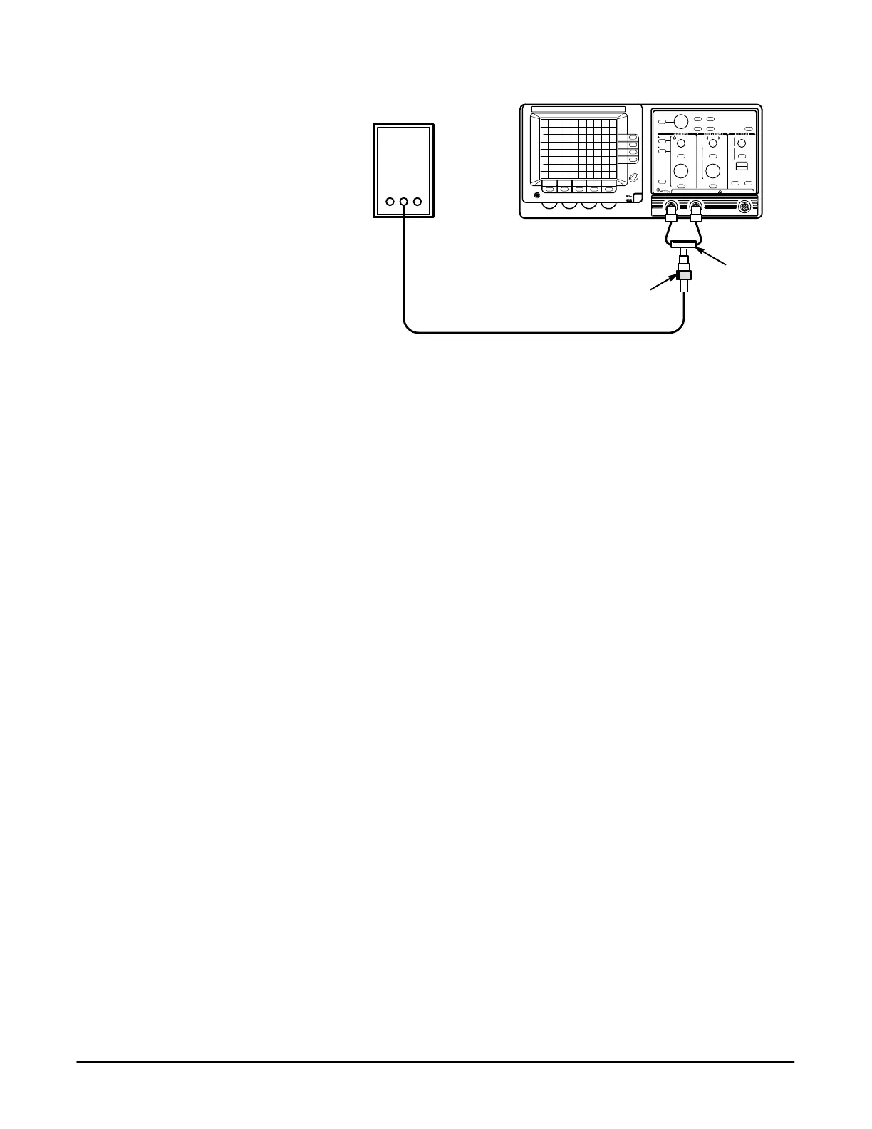
Pulse Generator
Precision Cable
50 W Termination
DualĆinput
Coupler
%$0-" 54*2 -",0") 3 0/+0/ *(+")./%*) '%-/%*) "/0+
8. Set the pulse generator for fast rise period of 1 ms and a 4 division
display.
9. Press the button.
10. Press the button and set D to ).
11. Set the cursors 5 divisions apart using the General Purpose Knob and
the button.
12. Set the volts/div scale to 20 mV.
13. Press the button.
14. Set the channel 2 volts/div scale to 20 mV.
15. Press the button and make the following selections
from the menu (channel 2):
H Set to
H Set to ##
H Set to ##
H Set to 0''
16. Position the channel 2 trace to the center vertical graticule line.
17. Set to .
18. Adjust R111 located on the Display Driver board for minimum vertical
movement of the readout (over the entire graticule area).
19. Disconnect the test setup from the oscilloscope.

 Loading...
