# !! "
# "
6Ć39
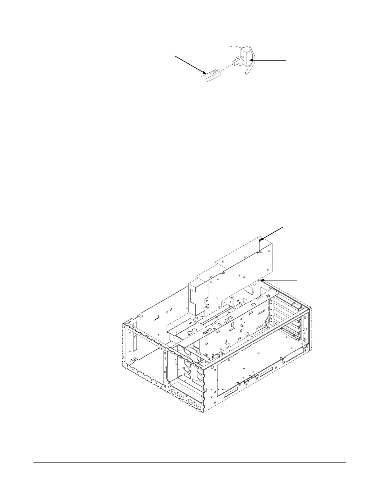
Power Switch
Located on Power
Supply Module
Power Button Shaft
" '&$ "!! ! !
3. Unplug the cables going to the A3 Display Driver board at J70 and J71.
4. Set the oscilloscope so its bottom down on the work surface.
5. Unplug the cable going to the A5 CPU board at J55.
6. Unplug the twoĆwide cable from the fan.
7. Unplug the red CRT anode lead from the power supply connector.
8. Remove the two screws securing the Power Supply module to the
chassis.
9. Lift the Power Supply module out of the chassis to complete its removal.
(See Figure 6Ć24.)
Mounting Screw (2)
Mounting Tab
" '&$ "% #

 Loading...
