*'*%& +,+
*." &-$
4Ć19
9. Disconnect the test setup from the oscilloscope.
10. Repeat this procedure until all input channels are verified.
!# 1/"+ "&
)-"(%&, )-"* One pulse generator (item 10) and one precision
coaxial cable (item 5).
1. Display channel 1, turning all others off.
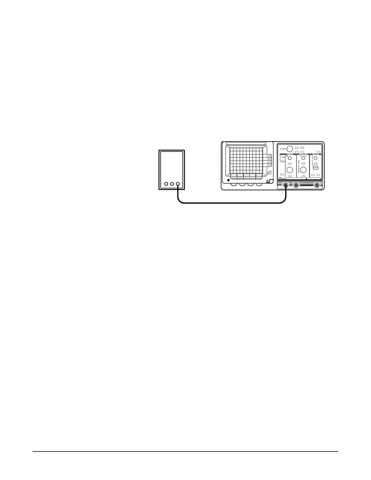
2. Connect the output of the pulse generator to the input as shown
Figure 4Ć9.
Pulse Generator
Precision Cable
" -* 101/"+ "& +, ,-(
3. Set the output of the pulse calibration generator for 50 mV.
4. Press the button.
5. Set the volts/div scale to 10 mV.
6. Center the display using the vertical control.
7. Press the button and set to &.
8. Check that the amplitude of the XĆaxis signal is 4.8 to 5.2 divisions.
9. Set to .
10. Disconnect the test setup from the oscilloscope.
 Loading...

