#(201*$+1 /,"$#2/$0
$/3'"$ +2 )
5Ć5
#(201*$+10
.2'-*$+1 $.2'/$# One time marker generator (item 9), one precision
coaxial cable (item 5), and one 50 W termination (item 3).
#(201*$+1 ," 1',+0 This procedure requires adjustments to the Display
Driver board. See Figure 5Ć14 on page 5Ć20 for the location of the adjustĆ
ments.
1. Disconnect all signal inputs from the oscilloscope.
2. Display channel 1, turning all others off.
3. Press the button.
4. Set the volts/div scale to 50 mV.
5. Set the sec/div scale to 2 ms.
6. Press the button and make the following selections
from the menu:
H Set to
H Set to 4
7. Position the channel 1 trace to the center horizontal graticule line and
adjust the control for a wellĆdefined display.
8. Adjust the control (screwĆdriver adjustment) to align
the trace with the center horizontal graticule line.
9. Press the button and set to +.
10. Set the control fully counterclockwise (off).
11. Adjust R321 on the Display Driver board until the dot is visible, then
reĆadjust R321 until the dot just extinguishes.
12. Set to %%.
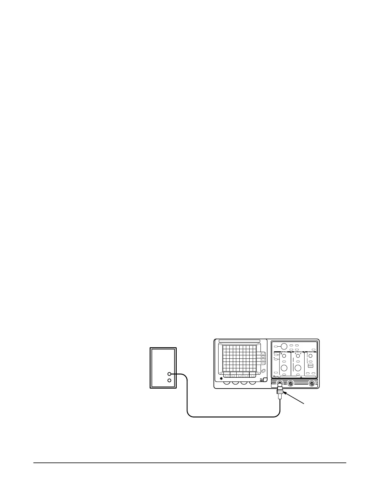
13. Connect the output of the time mark generator to the input as
shown in Figure 5Ć2.
Time Mark Generator
50 W Termination
Precision Cable
'&2/$ 65 #(201*$+10 )'!/ 1',+ $12-

 Loading...
