EasyManua.ls Logo

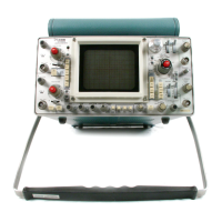
Tektronix 466

Tektronix 466
80 pages
To Next Page IconTo Next Page
To Previous Page IconTo Previous Page
Loading...
TIME DIFFERENCE BETWEEN TWO
PULSES FROM DIFFERENT SOURCES
(BASIC 466/464)
Make sure
the
VAR
TIME/DIV
control
is in the
calibrated detent. Set the A
Trigger
SOURCE
switch to CH
1.
Connect
the reference signal
to
CH
1 and the
com-
parison signal
to
CH
2.
Connect
the signals
to
the
input
connectors
using probes
or
cables
with
equal time delay.
CHANNEL 1 (REFERENCE)
I
I
100
90
I
....
....
50%
A MPLITUDE
LEVEL
\
0
I
0
....
. . . .
I
(A)
\
~\
v
,
~
F:::::
. . . .
~
I I I
INTENSIFIED
ZONE
....
/~i...
/ -
/
-0
-
-
:@
')
-
-
I
I
. . . . . . . .
. . . .
. .
-I
HORIZONTAL
I
- DIFFERENCE -
--i
'
'
CHANNEL2
v
I
/_
.
...
. . . .
MEASURE
TIME FROM
ATO
B
.
...
Set the VERT
MODE
switch
to
either
CHOP
or
ALT. In
general,
CHOP
is
more
suitable
for
low-frequency
signals
and
the
ALT
position
is
more
suitable
for
high-frequency
signals.
Center
each
of
the displays
vertically
(see Fig.
29A).
Set the
HORIZ
DISPLAY
switch
to
A
INT
and the B
Trigger
SOURCE
to
STARTS AFTER DELAY. Set the B
TIME/DIV
switch
20
times faster than the A
TIME/DIV
switch
(when possible).
r
100
9
~
10
I
~
(B
VERTICAL
REFERENCE
LINE
-
"""
~
-
.
...
. . . . . . . . . .. .
.
...
. .. .
CH
2
Sl~~AL
CH
1
SIGNAL
~It.
....,i'....:A
FOR
CH
1
B
FOR
CH
2
CH
1
SIGNAL
.....
.....
. . . . . . . .
.....
. . . .
-
-
--
-
)
-
1737·12
Fig.
29.
Time difference between two pulses
from
different
sources.
54
466/464 DM44
Operators
@
I
I
I
E
E
I
I
I

Table of Contents

Related product manuals