Fig. 2-2. Handle positioned to provide a stand for the instrument.
CAUTION
The Type 491 should not be operated with these
voltage selector switches in improper positions.
Operation of the instrument with incorrect voltages
will either blow the protective fuses or the instru-
ment will not operate properly.
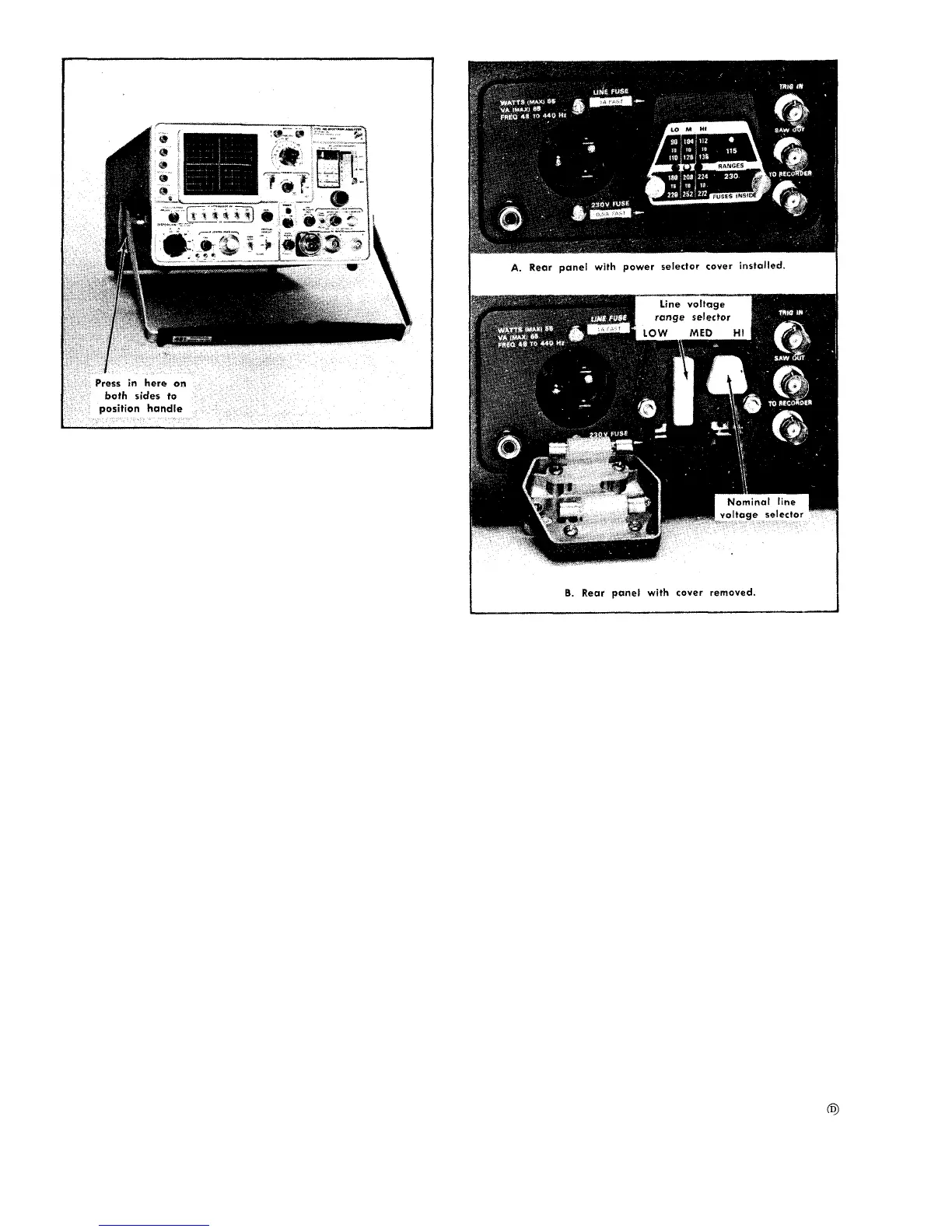
The Voltage Range Selector located on the rear panel
permits the instrument to operate on line voltages above and
below the nominal 115 or 230 volts. Each selection provides
correct regulation through an overlap voltage range into the
next higher or lower range. It is best to select a range with
its center voltage near your nominal line voltage, thus pro-
viding adequate regulation over a plus and minus devia-
tion of the input line voltage.
The following procedure will prepare the instrument for
operation at your average input line voltage:
1. Remove the cover assembly over the selectors by
unscrewing the two cap screws, then pull the cover with the
attached fuses away from the panel.
2. Pull the Line Voltage Selector out and turn the connector
around to plug it back into the correct position.
3. To change the regulating range, pull out the Range
Selector bar, slide it to the desired range and plug it into
the correct position. Select a range which is centered about
the average line voltage to be applied to the instrument.
See Fig. 2-3.
4. Re-install the cover. Make certain the cover fits firmly
against the rear panel, so the line fuses are seated in their
sockets, and tighten the two cap screws.
5. Before applying power to the instrument, check that the
indicating tabs on the switch bars are protruding through
the correct holes for the desired voltage setup.
2-2
Fig. 2-3. Power panel and selectors.
Spectrum Analyzer Terms
The following glossary of spectrum analyzer terms is pre-
sented as an aid to understanding the terms as they are used
in this manual.
Spectrum Analyzer-A device that displays a graph of the
relative power distribution as a function of frequency, typi-
cally on a cathode-ray tube or chart recorder.
Types: Real-time and non real-time.
A real-time spectrum analyzer performs a continuous
analysis of the incoming signal, with the time sequence of
events preserved between input and output.
A non-real-time spectrum analyzer performs an analysis
of repetitive events by a sampling process.
Methods: Swept front end and swept intermediate fre-
quency.
A swept front end spectrum analyzer is a superheterodyne
spectrum analyzer in which the first local oscillator is swept.
A swept IF spectrum analyzer is a superheterodyne spec-
trum analyzer in which a local oscillator other than the first
is swept.