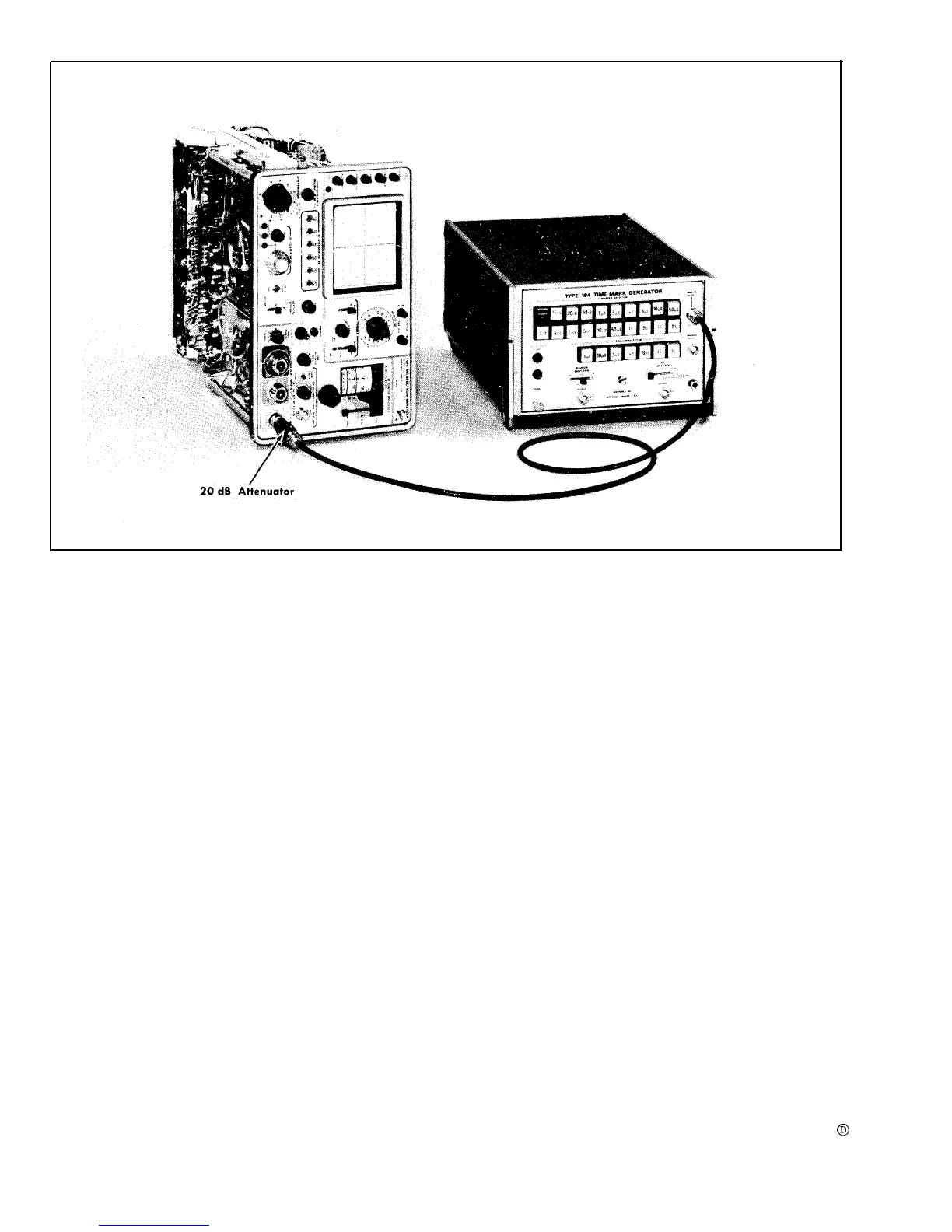
Fig. 6-29. Test equipment setup to adjust and check kHz/DIV dispersion accuracy.
Type 491
INTENSITY
FOCUS and ASTIGMATISM
SCALE ILLUM
POSITION (Horizontal and
Vertical)
TIME/DIV
VARIABLE
TRIGGER
SLOPE
LEVEL
SOURCE
DISPERSION RANGE
DISPERSION-COUPLED
RESOLUTION
IF ATTENUATOR
dB
IF CENTER FREQ
VIDEO FILTER
VERTICAL DISPLAY
6-26
Display of nominal
brightness
Adjusted for optimum
display definition.
As desired
Adjusted for a
horizontally centered
sweep on the graticule
baseline.
.1 s
CAL
+
Triggered sweep
LINE
kHz/DIV
500 kHz/div
All switches in off postion
Midrange (000)
OFF
LIN
OFF
VIDEO FILTER
GAIN
Midrange
POWER
ON
MIXER PEAKING
SEARCH
FINE RF CENTER FREQ Centered
PHASE LOCK Controls
INT REF FREQ OFF
24.
a.
Adjust kHz/DIV Dispersion
Equipment setup is shown in Fig. 6-29.
NOTE
An alternate setup to check kHz/div dispersion is
as follows: Replace the Coaxial Mixer for band C
with ‘the Waveguide Adapter. Apply the output of
the Time-Mark Generator (Type 184) through a
20 dB attenuator and a BNC to TNC adapter to
the band C RF INPUT. Switch the band selector to
band C. This permits the direct application of an
IF feedthrough signal. Markers down to 1 kHz/
div can now be readily observed over the range of
the IF CENTER FREQ control.