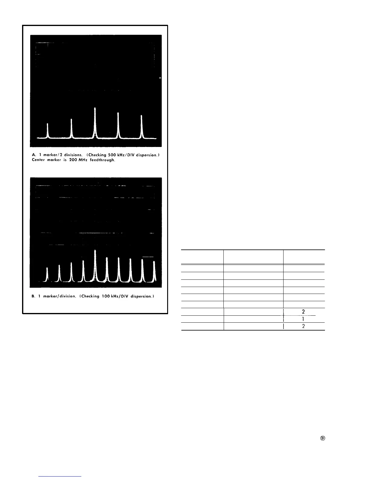
Fig. 6-31. Typical displays when checking or adjusting kHz/DIV
d. Center the IF CENTER FREQ controls and change the
DISPERSION to 50 kHz/div.
e. Apply 10 ns and 10 µs markers from the Time-Mark
Generatar to the RF INPUT.
f. Check-the range of the IF CENTER FREQ-FINE control.
Must equal or exceed 50 kHz either side af center.
g. Center the IF CENTER FREQ controls, change the DIS-
PERSION bock to 500 kHz/div and apply 10 ns and 1 µs
markers,
h. Check-the dispersion accuracy (Fig. 6-31) at each DIS-
PERSION selector position noted
in Table 6-5.
Measure dispersion accuracy within the center 8 div of the
display for each selector position and over the + and – 2.5
MHz range of the IF center frequency. Check the accuracy
with the IF CENTER FREQ control centered, then rotate the
control to the dial reading noted in step c for 2.5 MHz from
center, and check the dispersion accuracy.
Decrease the sweep speed as the dispersion is decreased,
and increase resolution by uncoupling the RESOLUTION
selector. Turn the control counterclockwise to optimize mark-
er definition. Switch the VERTICAL DISPLAY selector to LOG
and the VIDEO FILTER on at these slower sweep rates and
narrow dispersion settings.
i. Turn the VIDEO FILTER to OFF and the VERTICAL
DISPLAY selector to LIN.
TABLE 6-5
DISPERSION
Time-Mark Generator
Divisions per
kHz/DIV Marker Selector marker
500
10 ns and 1 µs
2
200
10 ns and 5 µs
1
100
10 ns and 10 µs
1
50
10 ns and 10 µS
2
20
10
ns and 50 µs
1
10
10 ns and .1 ms
1
5
10 ns and .1 ms
2
10 ns and .5 ms
1
10 ns and .5 ms
6-28