Fig. 2-10. 1 MHz MARKERS OUT (Phase lock reference) connector.
DISPERSION 1 MHz/div.
d. Adjust the DISPERSION-CAL for 1 marker/division.
Use the Horizontal POSITION control or the IF CENTER FREQ
control to align the markers to the graticule lines. Dispersion
is calibrated over the center 8 divisions of the display. See
Fig. 2-10.
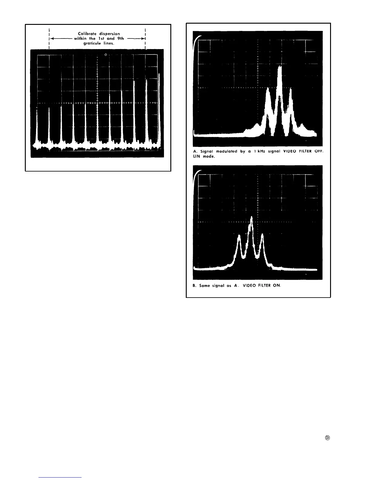
Video Filter Operation
The video filter restricts the video bandwidth so that noise
or beat signals are reduced. This application is very useful
when analyzing signals close to minimum resolution band-
width. Fig. 2-11 shows the apparent increased resolution
when the VIDEO FILTER is turned on. It does restrict the use-
able sweep rate, because of the filter time constant, to about
50 ms/div or slower.
Vertical Display Modes
The appearance of the displayed signal depends to a
great extent on the setting of the VERTICAL DISPLAY switch.
For example; to accentuate the side lobes of a signal, the
LOG (40 dB full screen) position should be used, as com-
pared to the SQ LAW (13 dB full screen) position. Fig, 2-12
illustrates the effect of each display mode or each position
of the VERTICAL DISPLAY switch.
The LOG position increases the dynamic range of the dis-
play by attenuating large amplitude signals more than small
amplitude signals. This produces a display which approxi-
mates a logarithmic response curve. The circuit is basically
a compression circuit, and is most effective when there are
large signal amplitude differences.
Fig. 2-11. Integrating the display with the video filter.
The SQ LAW (power) position provides a display that is
approximately proportional to the square of the input sig-
nal amplitude. The display, therefore, approximates the input
signal power. This is basically an expansion circuit to ac-
centuate small amplitude differences.
Selecting the Sweep Rate
The sweep rate for wide dispersion coupled resolution set-
tings is usually set just above the visual flicker setting; how-
ever, as the DISPERSION is decreased the sweep rate will
begin to affect the resolution and sensitivity of the analyzer,
as described under Obtaining Optimum Resolution. There-
fore, as the DISPERSION settings are reduced the sweep
rate should also be reduced to maintain sensitivity and resolu-
tion.
2-12