as the RF Section) is assigned a particular series of num-
bers. Table 4-1 lists the assigned component numbers for
the various circuits,
Switch wafers are identified by counting from the first
wafer, located behind the detent section of the switch, towards
the last wafer. For example, the designation 2R printed by
a switch section on a schematic,
as the rear side of the second
from the switch detent section.
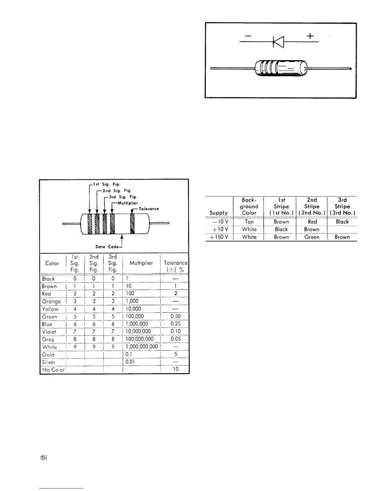
Resistor Color Code
identifies the switch section
wafer when counting back
The instrument contains a number of stable metal-film
resistors identified by their gray background color and color
coding. If a resistor has three significant figures and a
multiplier, it will be EIA color coded. If it has four signifi-
cant figures and a multiplier, the value will normally be
printed on the resistor. For example, a 332 resistor will
be color coded, but a 332.5 k resistor will have its value
printed on the resistor body. The color-coding sequence is
shown in Fig. 4-1.
Fig. 4-1. Standard EIA color code for metal-film resistors,
Fig. 4-2 identifies the polarity of the glass diode types
used in this instrument.
Wiring Color Code
The insulated wire used in the Type 491 is color-coded
according to the EIA standard color code to facilitate circuit
Fig. 4-2. Diode polarity for glass diodes.
tracing. The widest color stripe identifies the first color of
the code. Power supply voltages can be identified by three
color stripes and the background. White background indi-
cates a positive supply, and a tan background is used to
indicate a negative supply. Table 4-2 shows the wiring color
code for the power supply voltages used in the Type 491.
The color coding helps trace a wire from one point in the
instrument to another.
TABLE 4-2
RF cables for the RF and IF sections are miniature coaxial
cables. Some of these cables have a lossy characteristic
and are identified with a white outside coating, The stand-
ard 50 ohm low-loss coaxial cables have a clear plastic
outside coating. Do not interchange the lossy type with
the standard 50
Ω type when these coaxial cables are
replaced.
Removing and
Disconnect the
Replacing Assemblies
WARNING
instrument
before attempting repair
any sub-assembly.
Circuit Board Assembly
Replacement
If a circuit board assembly
from the power source
and/or replacement of
Removal or
is damaged beyond repair,
the entire assembly including all components should be
replaced. The board assembly part number is listed in the
Mechanical Parts List and may be ordered as directed.
In most cases the complete circuit board assembly should
be removed when components are to be replaced. This
will allow a soldering-iron tip to be placed at the back
side ar bottom of the board to unsolder the component
leads and remove the damaged component. The new com-
4-3