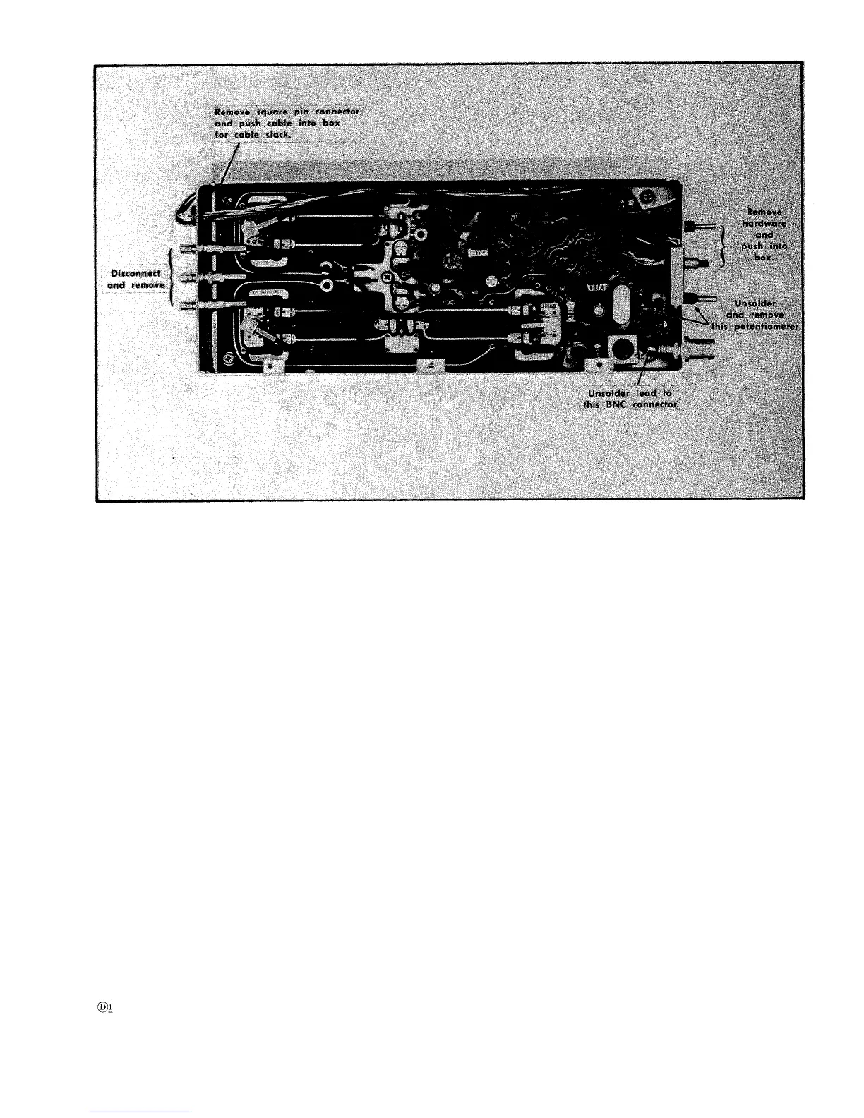
Fig. 4-16. Removing the phase-lock assembly board.
1. Band A Mixer Diodes
a. Disconnect the sub-miniature connectors, remove the
two mounting screws and the mixer assembly.
CAUTION
Do not tip or bend the connectors in removing
them. Grasp the body of the connector with the
fingers or needle nose pliers at the base of the
connector, and pull straight out.
b. Remove the four screws and spacers that hold the
cover and circuit plate to the shell.
c. Unsolder and replace the diodes with a matched pair.
See Fig. 4-18A. USE A HEAT SINK WHEN SOLDERING
THE NEW DIODES INTO PLACE, SEE SOLDERING TECH-
NIQUE.
e. Replace the cover and the mixer assembly. Reconnect
the connectors to the mixer assembly.
2. Band B Mixer Diode
a. Remove the front panel mounting nut and washer.
b. Slip the mixer assembly back and out of the unit.
c.
Unscrew the front barrel (1 dB pad) and replace the
mixer diode. See Fig. 4-18B.
3. Band C Mixer Diodes
a. Coaxial Mixer. Unscrew the base of the coaxial mixer.
Fig. 4-18C. Replace the diode and re-assemble the mixer.
b. Waveguide Mixers. Unscrew the cap over diode and
replace the-diode. See Fig. 4-18D.
Oscillator Tube Replacement
NOTE
A complete oscillator assembly
and its sub parts
are listed in the Mechanical Parts section. Replac-
ing components such as the oscillator tubes requires
a complete recalibration with special test equip-
ment and technique. We therefore recommend
replacing the complete assembly and returning the
defective assembly to your Tektronix Field office
or representative. A calibration procedure is pro-
vided in the Calibration section, if it is impractical
to return the assembly for repair.
The oscillator tube should only be replace after all tests
indicate the tube is faulty. Check supply voltages, etc., as
illustrated in Fig. 4-19A.
1. Band A and B oscillator tube replacement (V40 and V41)
a. Unscrew and remove the screws that hold the tap plate
to the oscillator chamber. Remove the top plate.
4-13