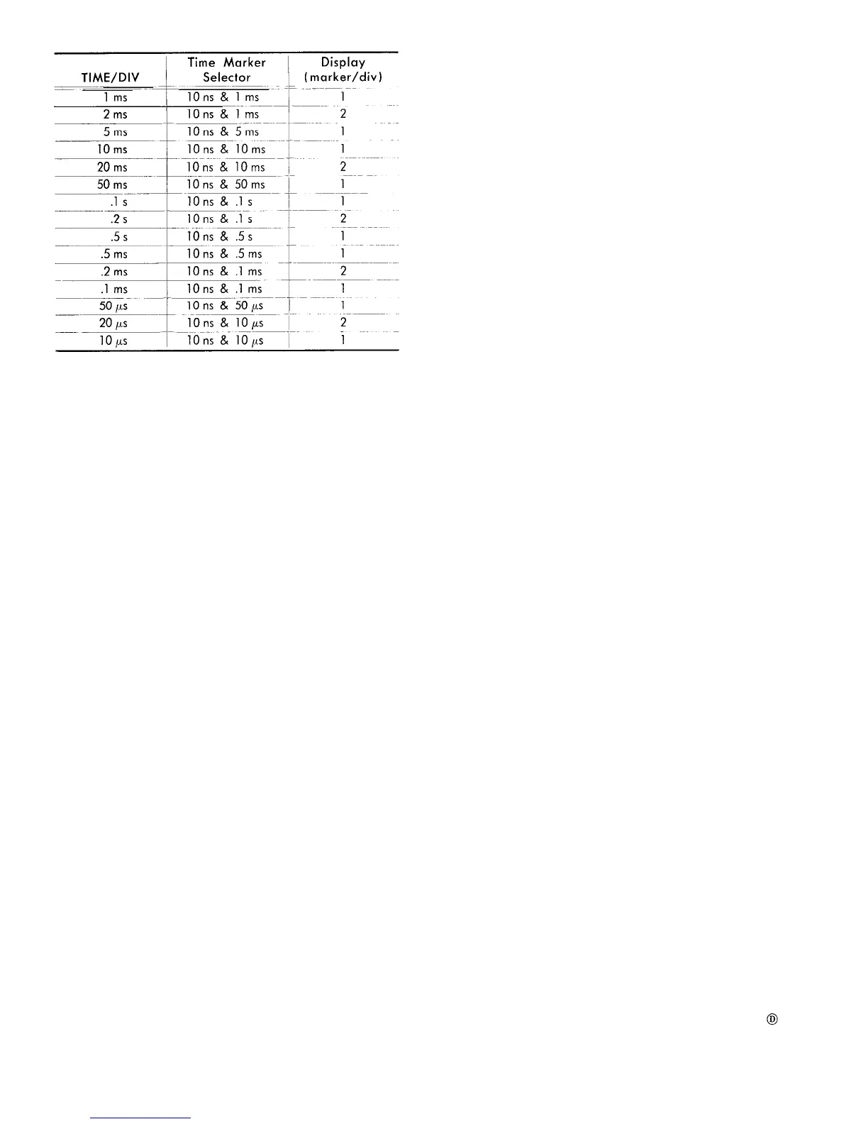
TABLE 5-1
10. Check Internal Triggering
a. Requirement-Sweep must trigger on 0.2 division signal
amplitude.
b. With 1 ms and 10 ns markers applied as in step 8,
adjust the Trigger LEVEL control for a triggered display on
the INT position.
c. Decrease the amplitude of the displayed markers by
switching in 20 dB attenuation and adjusting the GAIN con-
trol until sweep triggering can no longer be maintained
with optimum adjustment of the LEVEL control.
d. Check-Amplitude of the markers must be equal to
or less than 0.2 divisions (1 minor division).
11. Check IF Center Frequency
a. Requirement-The center frequency of the IF band-
pass with the IF CENTER FREQ controls centered must be
adjustable to 200 MHz with the IF CENTER FREQ CAL
adjustment.
b. Apply a calibrated 200 MHz signal from the Time-
Mark Generator (Type 184) to band B RF INPUT connector
through a 20 dB attenuator pad. (Signal input to the Type
491 should be less than -30 dBm to reduce the number
of spurious signals.)
c. Set the Type 491 front panel controls as follows:
POSITION
Position the trace to the
bottom graticule line
IF CENTER FREQ Centered (000)
FINE IF CENTER FREQ
Centered
DISPERSION RANGE
MHz/DIV
DISPERSION-COUPLED
10 MHz/div
RESOLUTION
RF INPUT Selector
B
d. Adjust the GAIN control for a signal amplitude of
6 divisions.
e. Adjust the IF CENTER FREQ CAL for minimum signal
shift as the DISPERSION control is rotated between 10 MHz/
div and .2 MHz /div.
f. Position the IF feedthrough signal to the center of the
graticule with the Horizontal POSITION control.
g. Set the DISPERSION control to the .2 MHz/div posi-
tion.
h. Adjust the DISPERSION BAL for minimum signal shift
as the DISPERSION RANGE is switched between MHz and
kHz positions. Set the DISPERSION RANGE to kHz.
i. Adjust the IF CENTER FREQ CAL for minimum signal
shift as the DISPERSION control is switched between 100 kHz/
div and 1 kHz/div positions.
j. Check-There should be less than ±2 major division
signal shift as the DISPERSION control is rotated down to
the 1 kHz/div position. The IF CENTER FREQ CAL adjust-
ment should not be against the stop.
k. Return the DISPERSION RANGE to MHz position and
the DISPERSION-COUPLED RESOLUTION control to 10 MHz/
div position.
12. Check the Dispersion Accuracy of the MHz/
DIV Ranges and the Range of the IF Center
Frequency Control
a. Requirement-Dispersion accuracy for the MHz/DIV
ranges is listed in Table 5-2. IF CENTER FREQ coarse con-
trol range should equal or exceed + and - 25 MHz from
its centered (000) position. Dispersion accuracy and display
linearity must remain within the listed specifications of Table
5-2 to the + and – 25 MHz positions of the control.
b. Apply .1µs and 10 ns time markers from the Time-Mark
Generator (Type 184) through a 20 dB attenuator to band
A RF INPUT connector.
c. Set the VERTICAL DISPLAY switch to LOG position.
Adjust the GAIN control for a display amplitude of approxi-
mately 6 divisions.
Set the SOURCE switch to LINE and
adjust the LEVEL control for a triggered display.
d. Center the IF CENTER FREQ controls.
e. Check the dispersion accuracy and linearity for each
MHz/DIV setting of the DISPERSION selector as listed in
Table 5-2. (See Figs. 5-2 and 5-3.) The Horizontal POSI-
TION control or the IF CENTER FREQ control may be used
to align the prime markers to the graticule divisions. As
the DISPERSION is decreased, the RESOLUTION control
should remain in the coupled position,
f. Check the range, dispersion accuracy and linearity of
the IF CENTER FREQ control in the 2, 1, .5 and .2 MHz
positions of the DISPERSION selector.
Range of the coarse control should equal or exceed +
and - 25 MHz from its centered position. It is checked
by rotating the control to both extreme positions from center
and noting the frequency shift of the .1µs or 10 MHz mark-
ers as the control is rotated. Dispersion accuracy and dis-
5-4
 Loading...


