from 10 MHz to 12.4 GHz over 50 MHz dispersion on band A
and over 100 MHz dispersion for bands B and C to 12.4
GHz. 6 dB maximum amplitude variation from 12.4 GHz
to 40 GHz, over 100 MHz dispersion.
NOTE
Display Flatness check for bands B and C must
be made with the MIXER PEAKING control adjusted
to maximize signal amplitude for each display
window.
b. Set the front panel controls as follows:
DISPERSION RANGE
MHz/DIV
DISPERSION
5 MHz/div
VERTICAL DISPLAY
LIN
IF ATTENUATOR
20 dB
Band Selector
A
TIME/DIV
5 ms
c. Apply the output signal from a signal generator with-
in the frequency range of band A through a 20 dB attenu-
ator, (Part No. 011-0086-00) to the band A RF INPUT con-
nector.
d. Set the generator frequency and the RF center fre-
quency to the frequencies that are listed in Table 5-5. Adjust
the signal generator output attenuator and the Type 491
GAIN control for a signal amplitude of 6 divisions.
e. Check band A display flatness by tuning the signal
from the left edge to the right edge of the display screen
with the RF CENTER FREQUENCY control. (Frequency range
+ and - 25 MHz from the RF center frequency.) Signal
amplitude should not change more than ±1.5 dB from its
average amplitude or 3 dB (2.4 div) total.
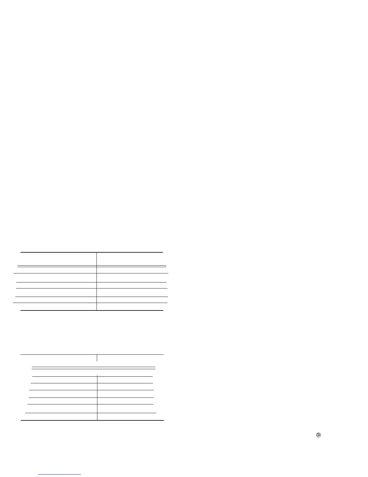
TABLE 5-5
RF Center
Applied Signal
Frequency Generator Freq.
10 MHz- 60 MHz 35 MHz
50 MHz-100 MHz
75 MHz
100 MHz-150 MHz
125 MHz
150 MHz-200 MHz
175 MHZ
200 MHz-250 MHz
225 MHz
250 MHz-275 MHz
275 MHz
f. Remove the signal to band A, RF INPUT and apply
a signal within the frequency range of band B to RF INPUT
B. Set the band selector to B and set the DISPERSION to
10 MHz/div.
TABLE 5-6
RF Center
Applied Signal
Frequency Generator Freq.
275 MHz-375 MHz 325 MHz
375 MHz-475 MHz
425 MHz
475 MHz-575 MHz 525 MHz
575 MHz-675 MHz 625 MHz
675 MHz-775 MHz
725 MHz
775 MHz-875 MHz
825 MHz
875 MHz-900 MHz
850 MHz
g. Check display flatness for band B as per Table 5-6.
Maximum amplitude variation over 100 MHz window (± 50
MHz from RF center frequency) must not exceed 3 dB. Ad-
just MIXER PEAKING for maximum signal amplitude before
measuring flatness.
h. Remove the signal from band B INPUT and apply the
output from signal generators, that cover scales 4 through
6 frequency range, to band B Coaxial Mixer.
i. Check response flatness through the frequency range
of the Coaxial Mixer. Maximum amplitude variation over
100 MHx dispersion window must not exceed 3 dB. Adjust
MIXER PEAKING for maximum signal amplitude before
measuring flatness.
j. Replace the Coaxial Mixer with the Waveguide Mixer
Adapter.
k. Apply the output from a signal generator, within the
frequency range of scale 8 and 9, through one of the Wave-
guide Mixers and the 2 foot cable (with TNC connectors)
to band C Waveguide Adapter.
l. Check response flatness for the frequency range above
12.4 GHz. Maximum amplitude variation over 100 MHz dis-
persion window must not exceed 6 dB (+2.4 div, -1.3 div).
Adjust MIXER PEAKING for maximum signal amplitude
before checking flatness.
m. Remove the Waveguide Adapter and replace the
Coaxial Mixer in the band C receptacle.
24A. Check RF Center Frequency Calibration,
System Sensitivity and Phase Lock Opera-
tion
NOTE
Since signal generators with calibrated attenuators
are required to check sensitivity, dial accuracy can
be checked by the same instruments provided the
signal source has an accuracy within 0.1% at the
dial check points. The signal generators listed in
Table 5-7 may be used if accuracy is checked near
each dial check point, by a frequency counter or
the beat frequency indicator against some accurate
reference frequency.
A secondary or alternate source of accurate fre-
quency markers is the combination of two calibra-
tion fixtures (Harmonic Generator 067-0594-00
and a 200 MHz Trap 067-0595-00) and a rela-
tively low frequency, accurate (at least 0.1%),
signal source such as a Time-Mark Generator
(Type 184).
The harmonic generatar will produce sufficient
harmonic signal power from the Type 184 to pro-
duce frequency markers into the GHz range. The
200 MHz trap attenuates the IF feedthrough spuri-
ous response.
This procedure is divided into two steps, with step
24B describing the dial check procedure using the
harmonic generator.
5-10
 Loading...


