Maintenance—492/492P Service Vol. 1 (SN B030000 & up)
TM 503 Main Frame
• I
θ · Φ
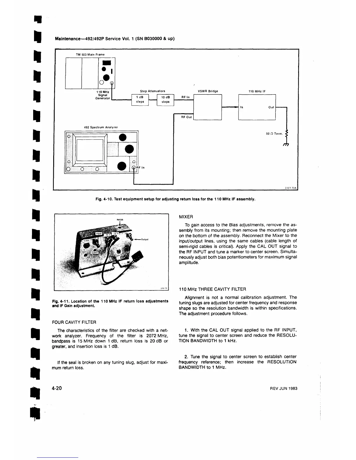
110MHz
Signal
Generator
Step Attenuators
VSWR Bridge
1 dB
10 dB
RF In
steps
steps
492 Spectrum Analyzer
a m m o
o
(pR F In
i
2727-72A
Fig. 4-10. Test equipment setup for adjusting return loss for the 110 MHz IF assembly.
Fig. 4-11. Location of the 110 MHz IF return loss adjustments
and IF Gain adjustment.
FOUR CAVITY FILTER
The characteristics of the filter are checked with a net
work analyzer. Frequency of the filter is 2072 MHz,
bandpass is 15 MHz down 1 dB, return loss is 20 dB or
greater, and insertion loss is 1 dB.
If the seal is broken on any tuning slug, adjust for maxi
mum return loss.
MIXER
To gain access to the Bias adjustments, remove the as
sembly from its mounting; then remove the mounting plate
on the bottom of the assembly. Reconnect the Mixer to the
input/output lines, using the same cables (cable length of
semi-rigid cables is critical). Apply the CAL OUT signal to
the RF INPUT and tune a marker to center screen. Simulta
neously adjust both bias potentiometers for maximum signal
amplitude.
110 MHz THREE CAVITY FILTER
Alignment is not a normal calibration adjustment. The
tuning slugs are adjusted for center frequency and response
shape so the resolution bandwidth is within specifications.
The adjustment procedure follows.
1. With the CAL OUT signal applied to the RF INPUT,
tune the signal to center screen and reduce the RESOLU
TION BANDWIDTH to 1 kHz.
2. Tune the signal to center screen to establish center
frequency reference; then increase the RESOLUTION
BANDWIDTH to 1 MHz.
4-20
REV JUN 1983
 Loading...


