Maintenance—492/492P Service Vol. 1 (SN B030000 & up)
2727-155
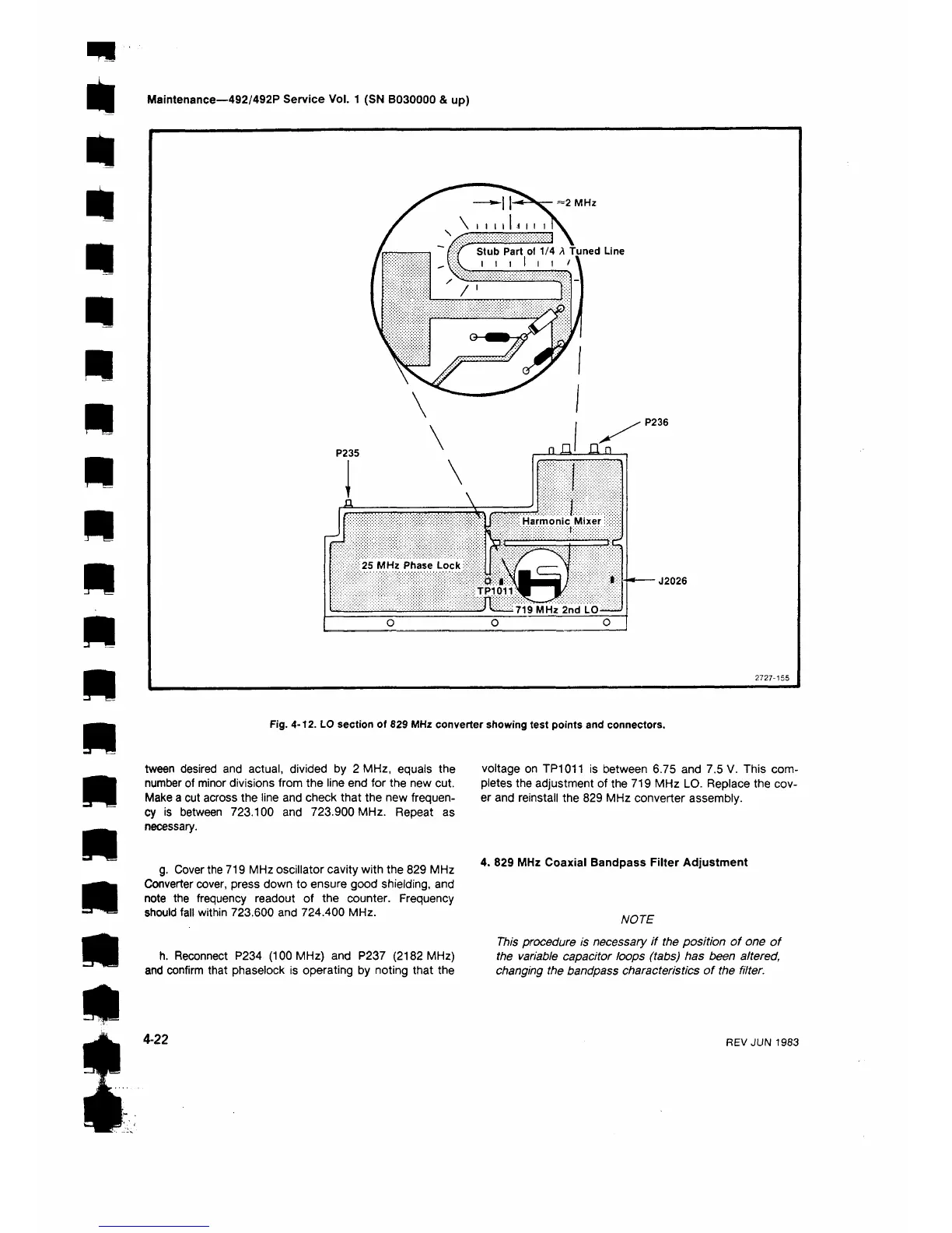
Fig. 4-12. LO section of 629 MHz converter showing test points and connectors.
tween desired and actual, divided by 2 MHz, equals the
number of minor divisions from the line end for the new cut.
Make a cut across the line and check that the new frequen
cy is between 723.100 and 723.900 MHz. Repeat as
necessary.
g. Cover the 719 MHz oscillator cavity with the 829 MHz
Converter cover, press down to ensure good shielding, and
note the frequency readout of the counter. Frequency
should fall within 723.600 and 724.400 MHz.
h. Reconnect P234 (100 MHz) and P237 (2182 MHz)
and confirm that phaselock is operating by noting that the
voltage on TP1011 is between 6.75 and 7.5 V. This com
pletes the adjustment of the 719 MHz LO. Replace the cov
er and reinstall the 829 MHz converter assembly.
4. 829 MHz Coaxial Bandpass Filter Adjustment
NOTE
This procedure is necessary if the position of one of
the variable capacitor loops (tabs) has been altered,
changing the bandpass characteristics of the filter.
4-22
REV JUN 1983
 Loading...


