Maintenance—492/492P Service Vol. 1 (SN B030000 & up)
Voltmeter
0 to -1 2 .5 V
Power Supply
8 8
QO
oo
□
ο φ φ
c
i r
~ + · ·
Q Q—
0
Θ O
1K Resistor
I
To 2182 MHz Tune I
2
I
Grounded to Housing
| 2182 MHz from Unbuffered Output Port
100 MHz Reference
Input
2nd LO Assembly
ΰ
o
o
i i i
492/492P Spectrum Analyzer (inverted)
r i H t
I © @ © @ @
100 MHz, 0 dBm Signal Generator
o o
Test Spectrum Analyzer
3783 -35 (3*8 1 -31)
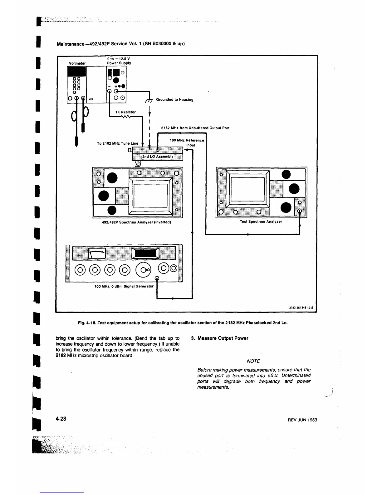
Fig. 4-18. Test equipment setup for calibrating the oscillator section of the 2182 MHz Phaselocked 2nd Lo.
bring the oscillator within tolerance. (Bend the tab up to 3. Measure Output Power
increase frequency and down to lower frequency.) If unable
to bring the oscillator frequency within range, replace the
2182 MHz microstrip oscillator board.
NOTE
Before making power measurements, ensure that the
unused port is terminated into 50 Ω. Unterminated
ports will degrade both frequency and power
measurements.
4-28
REV JUN 1983
 Loading...


