ύ
ύ
η
Maintenance—492/492Ρ Service Vol. 1 (SN B030000 & up)
■
m
w k
m
m
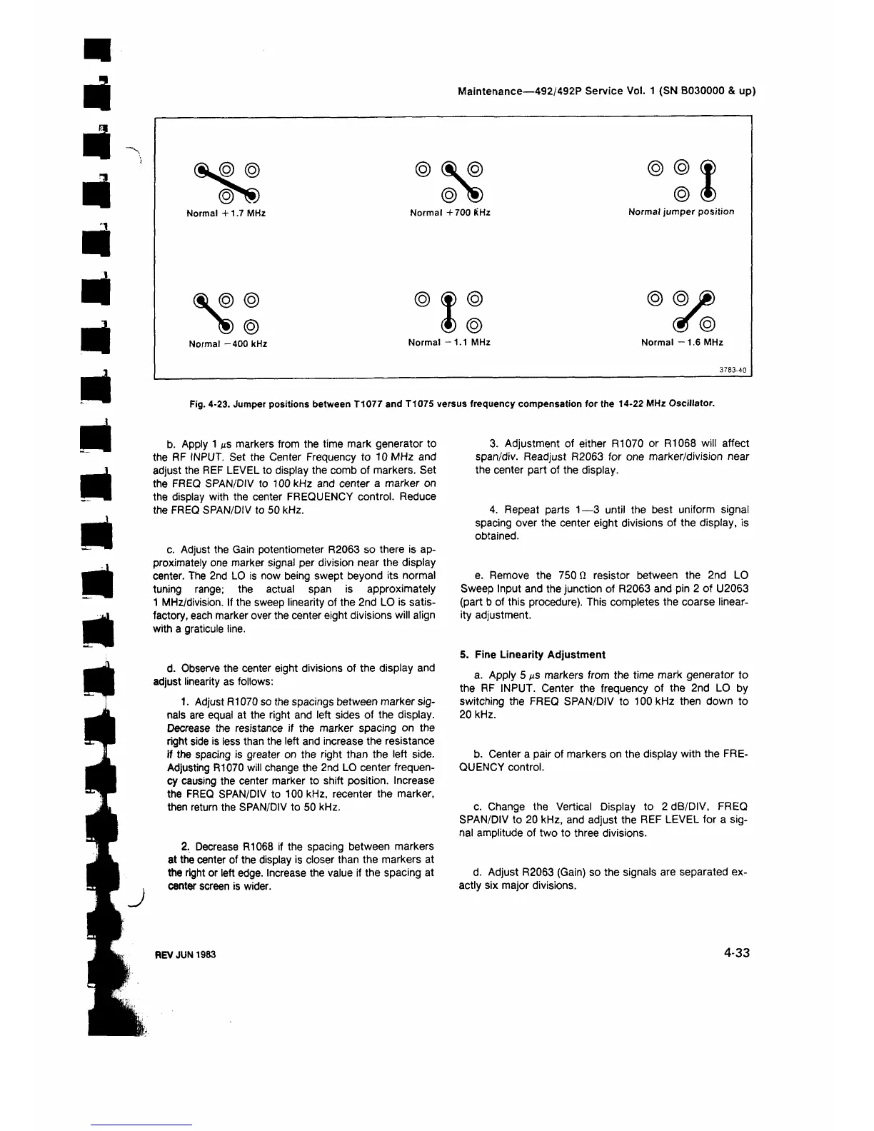
Fig. 4-23. Jumper positions between T1077 and T1075 versus frequency compensation for the 14-22 MHz Oscillator.
J
b. Apply 1 με markers from the time mark generator to
the RF INPUT. Set the Center Frequency to 10 MHz and
adjust the REF LEVEL to display the comb of markers. Set
the FREQ SPAN/DIV to 100 kHz and center a marker on
the display with the center FREQUENCY control. Reduce
the FREQ SPAN/DIV to 50 kHz.
c. Adjust the Gain potentiometer R2063 so there is ap
proximately one marker signal per division near the display
center. The 2nd LO is now being swept beyond its normal
tuning range; the actual span is approximately
1 MHz/division. If the sweep linearity of the 2nd LO is satis
factory, each marker over the center eight divisions will align
with a graticule line.
d. Observe the center eight divisions of the display and
adjust linearity as follows;
1. Adjust R1070 so the spacings between marker sig
nals are equal at the right and left sides of the display.
Decrease the resistance if the marker spacing on the
right side is less than the left and increase the resistance
if the spacing is greater on the right than the left side.
Adjusting R1070 will change the 2nd LO center frequen
cy causing the center marker to shift position. Increase
the FREQ SPAN/DIV to 100 kHz, recenter the marker,
then return the SPAN/DIV to 50 kHz.
2. Decrease R1068 if the spacing between markers
at the center of the display is closer than the markers at
the right or left edge. Increase the value if the spacing at
center screen is wider.
3. Adjustment of either R1070 or R1068 will affect
span/div. Readjust R2063 for one marker/division near
the center part of the display.
4. Repeat parts 1—3 until the best uniform signal
spacing over the center eight divisions of the display, is
obtained.
e. Remove the 750 Ω resistor between the 2nd LO
Sweep Input and the junction of R2063 and pin 2 of U2063
(part b of this procedure). This completes the coarse linear
ity adjustment.
S. Fine Linearity Adjustment
a. Apply 5 μ ε markers from the time mark generator to
the RF INPUT. Center the frequency of the 2nd LO by
switching the FREQ SPAN/DIV to 100 kHz then down to
20 kHz.
b. Center a pair of markers on the display with the FRE
QUENCY control.
c. Change the Vertical Display to 2 dB/DIV, FREQ
SPAN/DIV to 20 kHz, and adjust the REF LEVEL for a sig
nal amplitude of two to three divisions.
d. Adjust R2063 (Gain) so the signals are separated ex
actly six major divisions.
REV JUN 1983
4-33
 Loading...


