Theory of Operation—492/492P Service Vol. 1 (SN B030000 & up)
2072 MHz 2ND CONVERTER <φ>
The 2072 MHz 2nd Converter converts the 2072 MHz
signal output from the 1 st Converter to 110 MHz for eventu
al application to the 3rd Converter. The assembly consists
of a low-loss narrow-band four-cavity filter connected
through an internal cable to a low conversion loss narrow
band diode mixer, a 110 MHz lowpass filter, and a mixer
biasing circuit that wili disable the mixer when directed by
the microcomputer.
Four-Cavity Filter
The Four-Cavity (bandpass) Filter, which is depicted on
Diagrams 11, 12, and 13, is designed to pass only the
2072 MHz IF signal to the mixer and to reflect any other
frequencies back to the 1st Converter for termination. In
addition, the filter keeps the converter LO and mixer pro
ducts from entering the 1 st Converter.
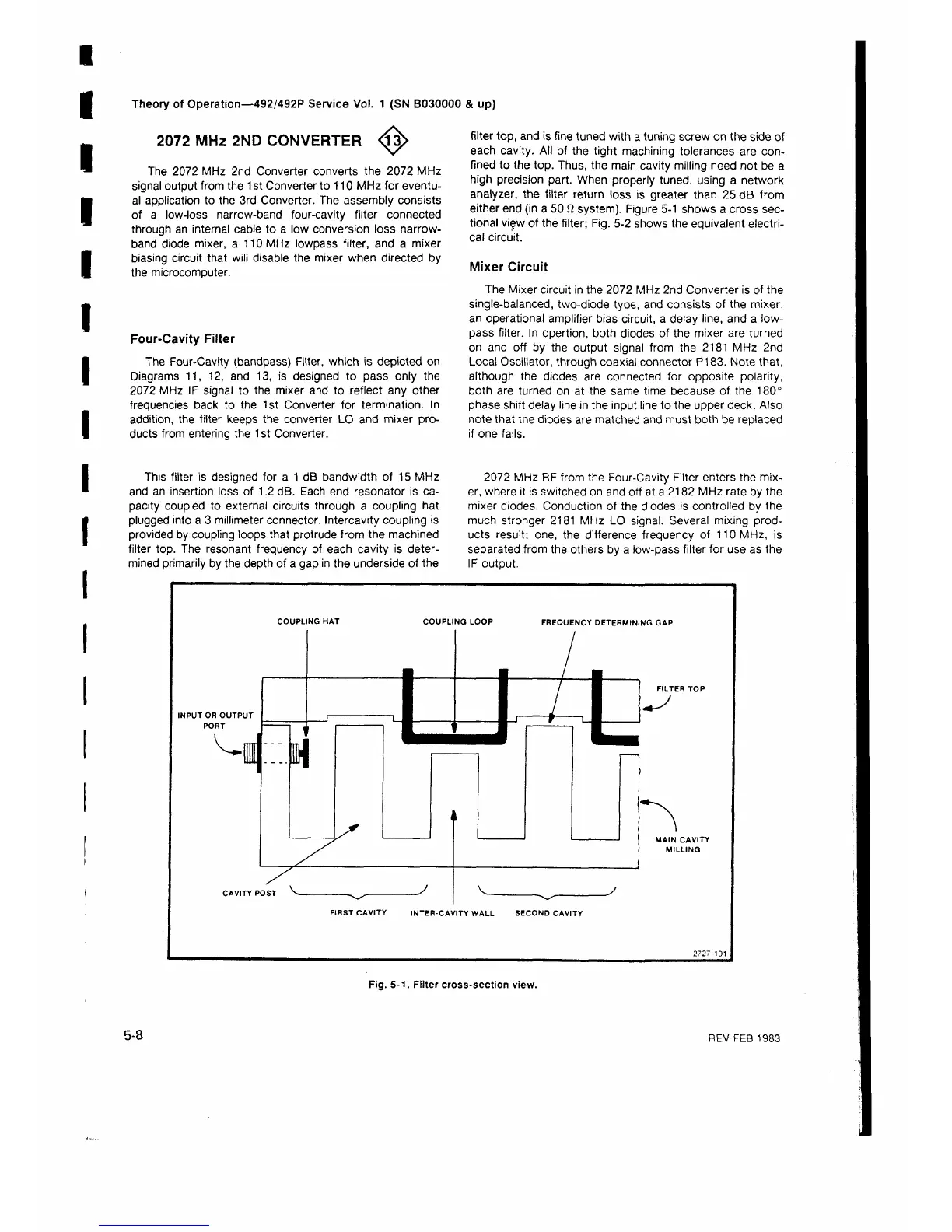
filter top, and is fine tuned with a tuning screw on the side of
each cavity. All of the tight machining tolerances are con
fined to the top. Thus, the main cavity milling need not be a
high precision part. When properly tuned, using a network
analyzer, the filter return loss is greater than 25 dB from
either end (in a 50 Ω system). Figure 5-1 shows a cross sec
tional vi<?w of the filter; Fig. 5-2 shows the equivalent electri
cal circuit.
Mixer Circuit
The Mixer circuit in the 2072 MHz 2nd Converter is of the
single-balanced, two-diode type, and consists of the mixer,
an operational amplifier bias circuit, a delay line, and a low-
pass filter. In opertion, both diodes of the mixer are turned
on and off by the output signal from the 2181 MHz 2nd
Local Oscillator, through coaxial connector P183. Note that,
although the diodes are connected for opposite polarity,
both are turned on at the same time because of the 180°
phase shift delay line in the input line to the upper deck. Also
note that the diodes are matched and must both be replaced
if one fails.
This filter is designed for a 1 dB bandwidth of 15 MHz
and an insertion loss of 1.2 dB. Each end resonator is ca
pacity coupled to external circuits through a coupling hat
plugged into a 3 millimeter connector. Intercavity coupling is
provided by coupling loops that protrude from the machined
filter top. The resonant frequency of each cavity is deter
mined primarily by the depth of a gap in the underside of the
2072 MHz RF from the Four-Cavity Filter enters the mix
er, where it is switched on and off at a 2182 MHz rate by the
mixer diodes. Conduction of the diodes is controlled by the
much stronger 2181 MHz LO signal. Several mixing prod
ucts result; one, the difference frequency of 110 MHz, is
separated from the others by a low-pass filter for use as the
IF output.
COUPLING HAT
COUPLING LOOP FREQUENCY DETERMINING GAP
INPUT OR OUTPUT
T n Q S E
,— , n
FILTER TOP
CAVITY POST
y
MAIN CAVITY
MILLING
FIRST CAVITY INTER-CAVITY WALL SECOND CAVITY
Fig. 5-1. Filter cross-section view.
5-8
REV FEB 1983
 Loading...


