Theory of Operation—492/492P Service Vol. 1 (SN B030000 & up)
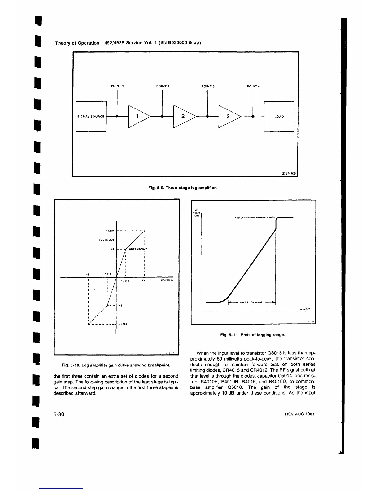
Fig. 5-9. Three-stage log amplifier.
2727-110
Fig. 5-10. Log amplifier gain curve showing breakpoint.
the first three contain an extra set of diodes for a second
gain step. The following description of the last stage is typi
cal. The second step gain change in the first three stages is
described afterward.
Fig. 5-11. Ends of logging range.
When the input level to transistor Q3015 is less than ap
proximately 60 millivolts peak-to-peak, the transistor con
ducts enough to maintain forward bias on both series
limiting diodes, CR4015 and CR4012. The RF signal path at
that level is through the diodes, capacitor C5014, and resis
tors R4010H, R4010B, R4015, and R4010D, to common-
base amplifier Q6010. The gain of the stage is
approximately 10 dB under these conditions. As the input
5-30
REV AUG 1981
 Loading...


