■
■
■
Theory of Operation—492/492P Service Vol. 1 (SN B030000 & up)
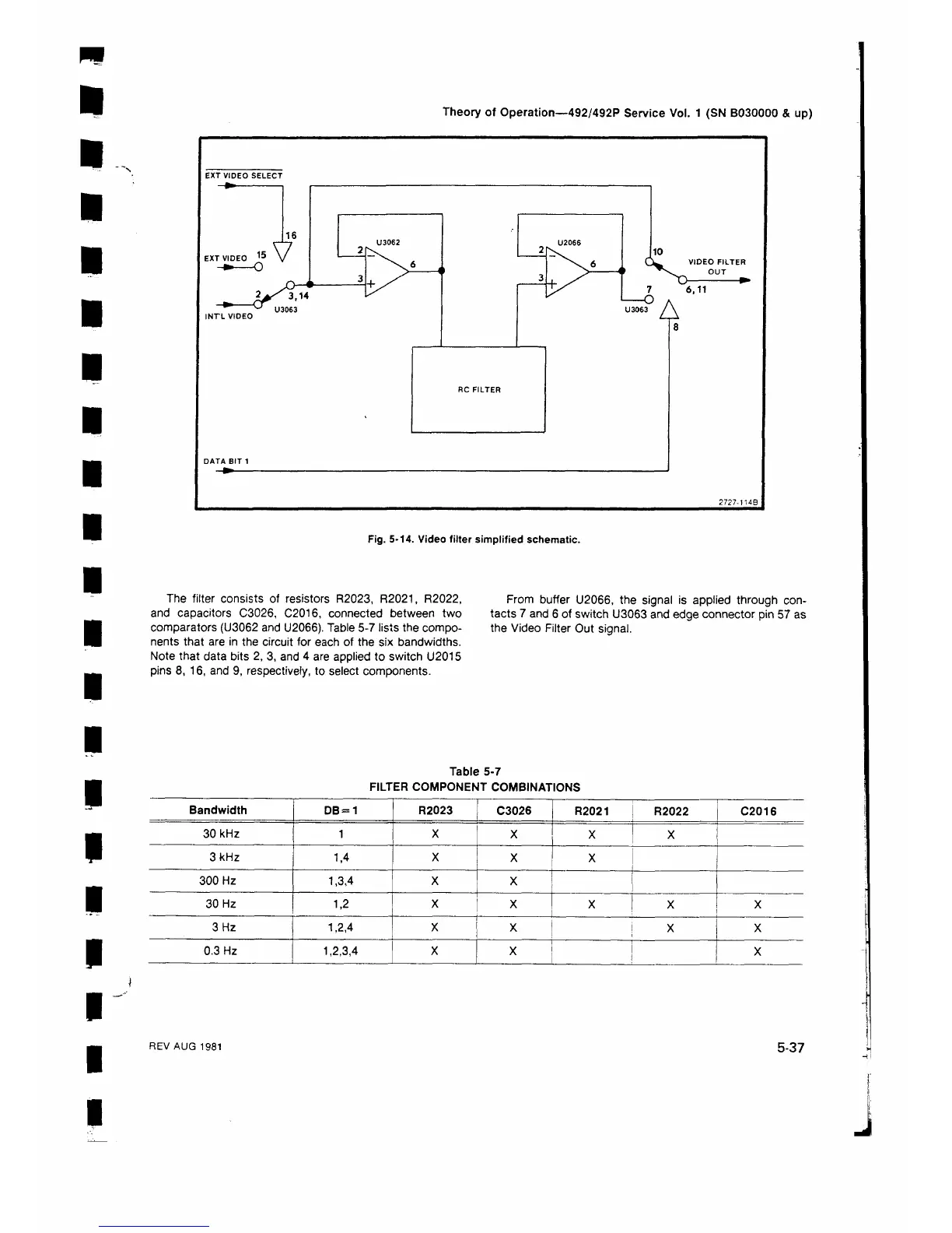
Fig. 5-14. Video filter simplified schematic.
The filter consists of resistors R2023, R2021, R2022,
and capacitors C3026, C2016, connected between two
comparators (U3062 and U2066). Table 5-7 lists the compo
nents that are in the circuit for each of the six bandwidths.
Note that data bits 2, 3, and 4 are applied to switch U2015
pins 8, 16, and 9, respectively, to select components.
From buffer U2066, the signal is applied through con
tacts 7 and 6 of switch U3063 and edge connector pin 57 as
the Video Filter Out signal.
Table 5-7
FILTER COMPONENT COMBINATIONS
I
I
I
I
Bandwidth
DB = 1 R2023 C3026
R2021
R2022 C2016
30 kHz 1 X
X
X X
3 kHz
1,4
X
X
X
300 Hz 1,3,4
X
X
30 Hz
1,2
X
X
X
X
X
3 Hz
1,2,4
X
X
! x
X
0.3 Hz 1,2,3,4
X
I
X i
X
REV AUG 1981
5-37
 Loading...


