Theory of Operation—492/492P Service Vol. 1 (SN B030000 & up)
sources. R1044 and R1053 protect CR2046 and CR2044
respectively, from external high voltage surges.
CRT READOUT <^>
The Crt Readout assembly stores readout characters
and generates deflection and Z-Axis signals to display the
characters. It also handles the frequency dot marker dis
play. Both characters and frequency dot displays are time-
shared with the spectrum trace.
Generating R eadout
Crt readout is handled by sequential logic, clocked at
3.41 MHz, supplied by the Processor board. The readout
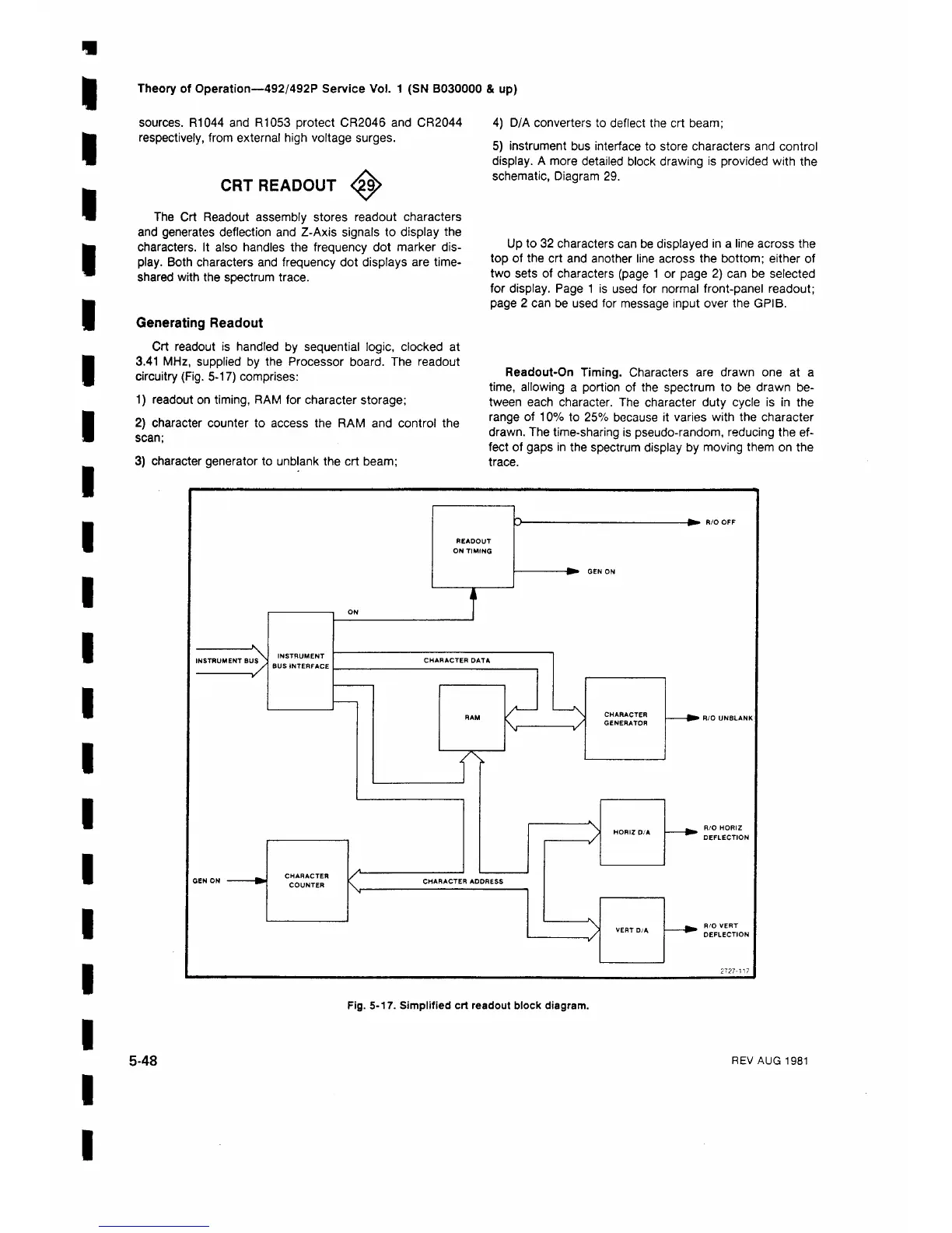
circuitry (Fig. 5-17) comprises:
1) readout on timing, RAM for character storage;
2) character counter to access the RAM and control the
scan;
3) character generator to unblank the crt beam;
4) D/A converters to deflect the crt beam;
5) instrument bus interface to store characters and control
display. A more detailed block drawing is provided with the
schematic, Diagram 29.
Up to 32 characters can be displayed in a line across the
top of the crt and another line across the bottom; either of
two sets of characters (page 1 or page 2 ) can be selected
for display. Page 1 is used for normal front-panel readout;
page 2 can be used for message input over the GPIB.
Readout-On Timing. Characters are drawn one at a
time, allowing a portion of the spectrum to be drawn be
tween each character. The character duty cycle is in the
range of 10% to 25% because it varies with the character
drawn. The time-sharing is pseudo-random, reducing the ef
fect of gaps in the spectrum display by moving them on the
trace.
Fig. 5-17. Simplified crt readout block diagram.
5-48
REV AUG 1981



 To Next Page