Pag
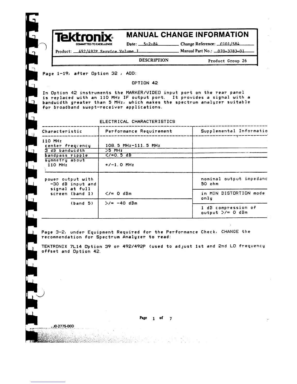
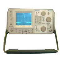
In Option 42 instruments the MARKER/VIDEO input port on the rear panel
is replaced with an 110 MHz IF output port. It provides a signal with a
bandwidth greater than 5 MHz, which makes the spectrum analyzer suitable
for broadband swept-receiver applications.
ELECTRICAL CHARACTERISTICS
Charac ter i st i c
Performance Requirement
Supplemental Informatio
110 MHz
center freqiency
108. 5 MHz-111. 5 MHz
3 dB bandwidth >5 MHz
bandpass ripple
</=0. 5 dB
symmetry about
110 MHz
i
+/-1. 0 MHz
power output with
-30 dB input and
signal at full
screen (band 1)
nominal output impedsnc
50 ohm
</= 0 dBm
in MIN DISTORTION mode
only
(band 5)
>/
---
40 dBm
1 dB compression of
output y / — 0 dBm
Ib k t r o n iX ® MANUAL CHANGE INFORMATION
coMMrTTED to EXCELLENCE Date: 5 -2 -8 4
_________
Change Reference: Π Π 1 /Sfl£
_____
P r o d u c t : & Q 7 /A Q ? P R p t -ι Η γ α V n l u m p
1--------------------------------Manual Part No.: —0 7 0 -3783- 0 1—
DESCRIPTION Product Group 26
e 1-19, after Option 32 , ADD:
OPTION 42
Page 3-2, un der Equi pment Required for the Performance Check, CHANGE the
recommendation for Spectrum Analyzer to read:
TEKTRONIX 7L14 Option 39 or 492/492P (used to adjust 1st and 2nd LO frequency
offset and Option 42.
Page i of 7
. JO-2775-OOD



 To Next Page