Product: 492/492P Service Vol.
_
1
--------
Date: 5-2-84
_________
Change Reference: Γ10]/5Β4
DESCRIPTION
Page 3-80, ADD after the adjustment for Phaselock Calibration:
14. For Option 42 instruments. Adjustment of Option 42 Module. This
adjustment need only be done after the circuit board in the module has been
replaced.
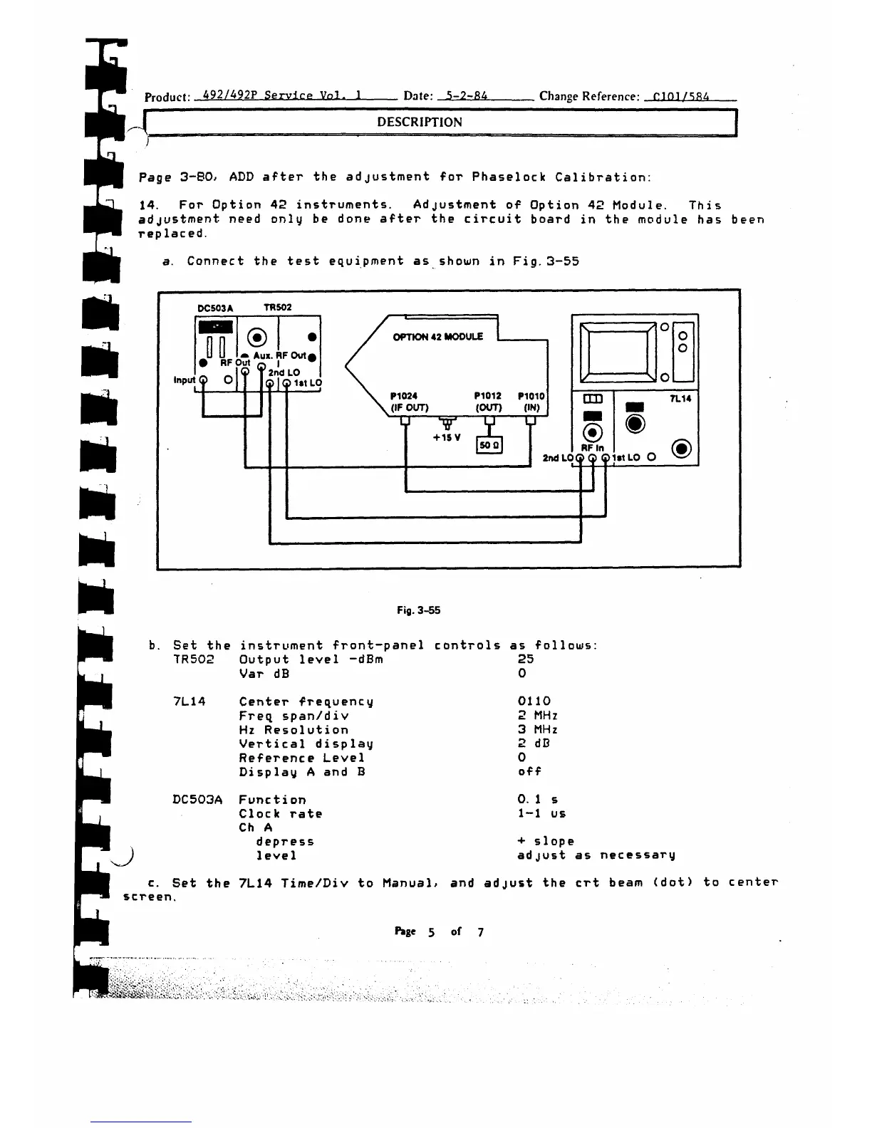
a. Connect the test equipment as shown in Fig. 3-55
Fig. 3 - 5 5
Set the instrument front-panel
controls as follows
TR502
Output level -dBm
25
Var dB
0
7L14
Center frequency
0110
Freq span/div
2 MHz
Hz Resolution
3 MHz
Vertical display
2 dB
Reference Level
0
Display A and B
off
0 . 1 S
1-1 us
+ slope
adjust as necessary
st the crt beam (dot) to center
screen.
Page 5 of 7
DC503A
vJ
Func ti on
Clock rate
Ch A
depress
1 eve 1
c. Set the 7L14 Time/Div to Manual, and adju



 To Next Page