Calibration—492/492P Service Vol. 1 (SN B030000 & up)
Performance Check
f. If the instrument has Option 01, check IM distortion as
follows:
1) change the FREQUENCY RANGE to band 2 (1.8 GHz
or higher), FREQ SPAN/DIV to 50 MHz, and RESOLU
TION BANDWIDTH to 100 kHz. Apply two signals above
1.8 GHz. Establish a full screen reference level by adjust
ing the output of the signal generator;
2) reduce the FREQ SPAN/DIV and RESOLUTION
BANDWIDTH so the noise floor is more than 70 dB down
from the reference level. Check for IM products.
Sidebands must be 70 dB or more below the signal level;
3) change the frequencies of the signal generators to fre
quencies within the 1.6—1.8 GHz range and the level to
-40 dBm;
4) using the above procedure, measure IM distortion. IM
products must be 70 dB or more down from the
-40 dBm signal level.
18. Check Harmonic Distortion (—60 dBc or
— 100 dBc for Option 01, below the level of a full
screen signal in MIN DISTORTION mode)
a. Set the front-panel controls as follows:
FREQUENCY RANGE Band 1
FREQ SPAN/DIV 5 MHz
AUTO RESOLUTION On
Vertical Display 10 dB/DIV
REF LEVEL -3 0 dBm
MIN RF ATTEN 0 dB
Video Filter WIDE
Digital Storage (Option 02) VIEW A/VIEW B
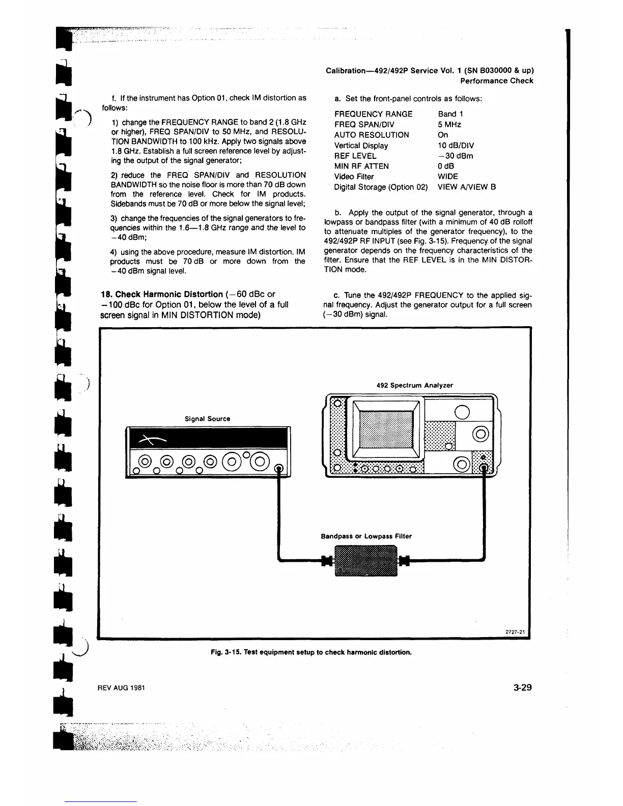
b. Apply the output of the signal generator, through a
lowpass or bandpass filter (with a minimum of 40 dB rolloff
to attenuate multiples of the generator frequency), to the
492/492P RF INPUT (see Fig. 3-15). Frequency of the signal
generator depends on the frequency characteristics of the
filter. Ensure that the REF LEVEL is in the MIN DISTOR
TION mode.
c. Tune the 492/492P FREQUENCY to the applied sig
nal frequency. Adjust the generator output for a full screen
(—30 dBm) signal.
Signal Source
n @ n ® o © a ©
@ ° @ ®
492 Spectrum Analyzer
W:· t
\
..
.
.....
/
o \
II ®
'
.
.
M(
Bandpass or Lowpass Filter
27 2 7 -2 1
Fig. 3-15. Test equipment setup to check harmonic distortion.
REV AUG 1981
3-29
 Loading...


