The Probe Compensation connections provide a ground connector and 1 kHz square wave source for adjusting the high-frequency
response of a passive probe (probe compensation). The oscilloscope uses this signal to automatically compensate supported probes.
See Compensate the TPP Series probes on page 42.
You can also use the ground connector to attach an anti-static wrist strap, to reduce the chance of electrostatic damage (ESD) while
you handle or probe the DUT.
4. USB Host ports: USB ports are located at the lower right corner of the front panel. Connect USB flash drives to which you can save or
recall data (such as instrument firmware updates, waveforms, settings, and screen captures), or connect peripheral devices such as a
mouse or keyboard.
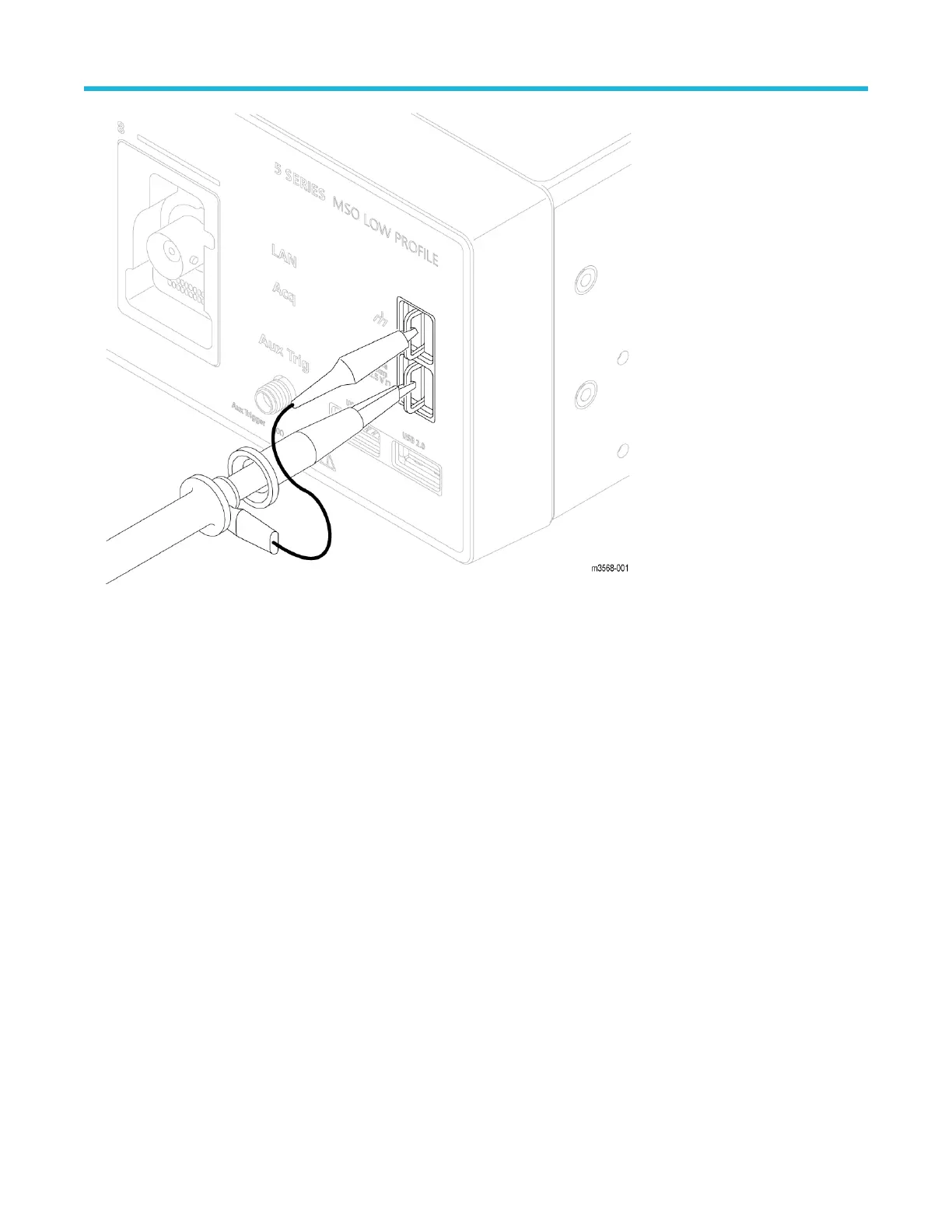
5. Aux Trig trigger input connector: An SMA connector to which you can connect an external trigger input signal. Use the AUX In
trigger signal with the Edge trigger mode.
6. Acq status LED: Shows the instrument trigger/acquisition status:
• Green - Triggered
• Yellow - Armed but not yet triggered
• Red - Acquisition stopped
7. Power On/Standby button: Powers the instrument on and off. The power button color indicates instrument power states:
• No light - No AC power applied
• Yellow - Standby mode
• Blue - Powered on
Getting acquainted with your instrument
22

 Loading...


