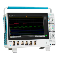


Do you have a question about the Tektronix MSO54 and is the answer not in the manual?
General safety precautions to avoid injury and prevent damage to products.
Safety instructions related to fire and personal injury prevention.
Precautions for safe operation, including covers, circuitry, conditions, and environment.
Understanding and respecting voltage ratings when using probes.
Additional information for safe service procedures by qualified personnel.
Explains how the power supply board converts AC to DC for internal circuits.
Details the functions of the Carrier interface assembly, including I/O and processor.
Describes the functions of the Main and Analog boards, including acquisition.
Precautions to avoid electrostatic discharge damage to components during service.
Describes how to inspect for dirt/damage and clean the instrument.
Procedure to remove and replace the rear chassis assembly to access internal components.
Procedure to remove and replace the power supply assembly from the rear chassis.
Steps for removing the power supply board and shield from the bracket.
Disconnecting power supply cables and fan cable from the carrier interface assembly.
A flowchart to determine the action for a fault condition in the instrument.
Procedure to determine if the power supply is defective and requires replacement.
| Analog Channels | 4 |
|---|---|
| Sample Rate | 6.25 GS/s |
| Vertical Resolution | 12-bit |
| Form Factor | Benchtop |
| Probe Interface | TekVPI |
| Operating Temperature | 0 °C to +50 °C |
| Bandwidth | 1 GHz |
| Record Length | 62.5 Mpoints |
| Display | 15.6 inch HD |
| Waveform Update Rate | >500, 000 wfms/s |
| Trigger Types | Edge, Pulse, Runt, Logic, Serial |
| Serial Bus Support | I2C, SPI, RS-232/422/485/UART, CAN/CAN FD/LIN, USB 2.0, Ethernet |
| Connectivity | USB, Ethernet |
| Input Impedance | 1 MΩ |
| Power Requirements | 100-240 VAC, 50/60 Hz |
| Maximum Input Voltage | 400 V (DC + peak AC) |


