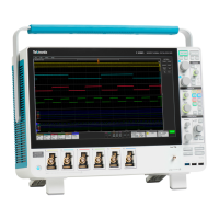
Do you have a question about the Tektronix MSO5000 Series and is the answer not in the manual?
Defines safety terms used in the manual and symbols found on the product for hazard identification.
Details EMC and safety standards, directives, and declarations the instrument complies with.
Information on product end-of-life handling, WEEE, and hazardous substances.
Highlights instrument capabilities and provides guidance on available documentation.
Lists standard accessories and specifies operating requirements like environment and ESD.
Covers ESD prevention, powering, securing, network connection, and OS restore.
Describes front, side, rear panels, interface elements, and display.
Details control panel functions and methods for accessing online help and menus.
Procedure to run and verify internal diagnostic tests for instrument functionality.
Procedures for signal path compensation and setting up analog signal input.
Explains acquisition modes, concepts, and default/autoset procedures.
Covers FastAcq, DSP bandwidth, roll mode, digital setup, and bus setup.
Introduces trigger concepts, types, and conditions for signal triggering.
Details trigger setup procedures including serial, parallel, email, and delay.
Options for display styles, persistence, formats, and waveform interpolation.
Tools for waveform zooming, navigation, marking, mask, and limit testing.
Guides on creating, opening, using, and editing custom MyScope control windows.
Procedures for saving/recalling screen captures, waveforms, and instrument setups.
Saving digital waveforms, measurements, masks, histograms, timestamps, and clipboard operations.
Lists and describes available application software for the instrument.
Examples for capturing anomalies and efficient documentation using extended desktop.
Demonstrates triggering on buses/video and correlating oscilloscope/logic analyzer data.
Procedures for cleaning the instrument and using TPP0500/TPP1000 passive probes.
Lists probe accessories, specifications, performance graphs, and safety summaries.
Instructions for connecting and using the P6616 general-purpose logic probe.
| Analog Channels | 4 |
|---|---|
| Operating Temperature | 0 °C to +50 °C |
| Digital Channels | 16 (MSO models) |
| Sample Rate (Analog) | 6.25 GS/s |
| Record Length | 125 Mpoints |
| Vertical Resolution | 8 bits |
| Display | 10.4-inch capacitive touchscreen |
| Connectivity | USB |
| Input Impedance | 1 MΩ |
| Trigger Types | Edge, Pulse Width, Logic, Setup/Hold, Rise/Fall Time, Video |


