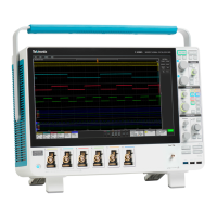
Do you have a question about the Tektronix MSO5054B and is the answer not in the manual?
General safety precautions to avoid injury and product damage.
Safety precautions for performing service procedures on the product.
Details on Electromagnetic Compatibility standards and declarations for the instrument.
Information on safety standards and certifications the product adheres to.
Specifies environmental and operational conditions for instrument models.
Procedures to prevent Electrostatic Discharge damage to the instrument input.
Instructions for powering the instrument on, off, and removing the power source.
Procedure for restoring the instrument's operating system from the hard disk.
Instructions for installing the hard drive assembly into MSO5000B/DPO5000B instruments.
Procedure to run and verify the results of the instrument's internal diagnostic tests.
Procedure to ensure measurement accuracy by compensating the signal path.
Steps to connect and select analog input channels for signal acquisition.
How to quickly return to factory defaults or use Autoset for automatic setup.
Explains acquisition hardware, sampling processes, and various acquisition modes.
Procedure for selecting and changing the instrument's acquisition mode.
How to start/stop acquisitions and select horizontal modes for testing.
Features for capturing events, enhancing bandwidth, and setting termination voltage.
Using Roll Mode for strip chart display and setting up digital signal inputs.
How to configure digital channels, buses, and display settings.
Guides on selecting and configuring various trigger types and their conditions.
How to check the instrument's trigger status using front panel controls and readouts.
Procedure for setting up sequential triggering using A and B trigger events.
How to set up triggers for parallel and serial bus signals.
How to use Wave Inspector controls for efficient management of long record length waveforms.
How to select channels and measurements for automatic analysis.
How to use cursors for manual measurements on acquired waveform data.
How to compare signals against predefined masks for compliance testing.
How to compare active signals against template waveforms for pass/fail testing.
Example procedure for capturing elusive intermittent anomalies using FastAcq and triggering.
How to set up triggers for various bus protocols like I2C, SPI, USB, and CAN.
| Bandwidth | 500 MHz |
|---|---|
| Channels | 4 |
| Sample Rate | 5 GS/s |
| Vertical Resolution | 8 bits |
| Power Supply | 100-240 VAC, 50/60 Hz |
| Display Type | LCD |
| Input Impedance | 1 MΩ |
| Operating System | Windows |
| Interface | USB, LAN |
| Display | XGA color TFT LCD |
| Display Size | 10.4 in |


