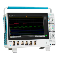
Do you have a question about the Tektronix MSO5204B and is the answer not in the manual?
General safety precautions to avoid injury and prevent product damage.
Safety guidelines to prevent fire and personal injury during operation.
Safety information for performing service procedures on the product.
Details the environmental and operational conditions for instrument setup.
Instructions on how to prevent electrostatic discharge damage to the instrument.
Information on power supply requirements for the instrument.
Procedure for safely powering down the instrument.
Procedure for restoring the instrument's operating system from disk.
Explains the instrument's user interface elements and display features.
Describes the functions of the front panel controls for MSO/DPO70000/DPO7000C series.
Details the front panel controls for MSO5000B and DPO5000B series instruments.
Procedure to run and verify the results of internal instrument diagnostics.
Procedure to calibrate the instrument's signal path for accurate measurements.
Steps for connecting and configuring analog signal inputs for acquisition.
Instructions for using the Autoset function to automatically configure acquisition settings.
Detailed guide on using Autoset for quick and automatic instrument setup.
Procedure for changing the instrument's acquisition mode.
Steps for initiating and halting waveform acquisitions.
Explains core concepts of trigger events, modes, and holdoff for precise triggering.
Utilizing A and B triggers for sequential event capture and complex triggering.
Guide to selecting and configuring various trigger types available on the instrument.
Lists and describes different trigger types and their conditions.
How to check the status of triggers using front panel controls and display readouts.
Procedure for using A and B triggers for capturing complex signals.
Adjusting trigger position for accuracy on displayed waveforms, especially noisy signals.
Using B-Event Scan for overlapped eye diagrams synchronized by an A trigger event.
How to locate problems by triggering on parallel bus signals.
Procedure for locating problems by triggering on serial bus signals.
Creating trigger conditions directly on the display screen using visual trigger areas.
Configuring the instrument to save files or send e-mails upon specific events.
Acquiring waveform detail in a region separated from the trigger location by time.
Utilizing Wave Inspector controls for efficient work with long record length waveforms.
Manually or automatically marking and searching for regions of interest in waveforms.
Procedure for performing automatic measurements on waveforms.
Utilizing the Serial Error Detector for Bit, Frame, Symbol, and Character error analysis.
Comparing signals to predefined templates or masks for test compliance.
Comparing active signals to template waveforms for pass/fail testing.
Using FastAcq and triggering to capture infrequent signal anomalies.
Setting up triggers for various bus types (I2C, SPI, USB, CAN, etc.).
Configuring the instrument to trigger on video fields (NTSC, SECAM, PAL).
Summarizes essential safety precautions for using the P6616 logic probe.
| Bandwidth | 2 GHz |
|---|---|
| Channels | 4 |
| Operating Temperature | 0 °C to +50 °C |
| Display | 12.1-inch LCD |
| Vertical Resolution | 8 bits |
| Input Impedance | 1 MΩ |
| Trigger Types | Edge, Pulse Width, Runt, Video |
| Sample Rate | 10 GS/s (all channels) |


