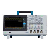
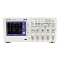
Do you have a question about the Tektronix TBS2204B and is the answer not in the manual?
Provides general precautions for safe operation to avoid injury and product damage.
Details precautions against fire and electrical shock hazards during use.
Guidelines for safe connection and use of probes and test leads.
Information for qualified personnel performing service procedures safely.
Instructions for unpacking and checking standard accessories before initial setup.
Step-by-step guide for installing license files to enable oscilloscope features.
Highlights the primary capabilities and functionalities of the TBS2000B oscilloscopes.
Details how to upgrade oscilloscope bandwidth using software licenses.
Specifies the operating temperature, humidity, and altitude limits for the instrument.
Details the required power source voltage, frequency, and consumption.
Instructions for connecting power, turning the oscilloscope on and off.
Procedure to change the on-screen display, measurements, and menus to 11 languages.
Instructions on how to connect probes or cables to the oscilloscope.
Explains how signals are measured, digitized, and stored into waveform records.
Explains how triggers are used to stabilize waveforms for measurement.
Details how signal slope and voltage level are used for triggering.
Configures how the input signal is passed to the oscilloscope sampling circuit (DC or AC).
Adjusts the maximum frequency range for accurate signal display and measurement.
Compensates for signal delays between channels for accurate time measurements.
Configures the oscilloscope to trigger on the rising or falling edge of a waveform.
Sets the oscilloscope to trigger on pulses based on their width.
Defines how the oscilloscope behaves in the presence or absence of a trigger.
Quickly acquires and displays a stable waveform by automatically adjusting settings.
Instructions for initiating waveform acquisition using Run/Stop or Single buttons.
Determines the number of sample points added to a waveform record.
Procedure to turn the display of each channel's waveform on or off.
Controls how long sampled waveform points are retained and displayed on screen.
Plots Channel 1 (X) against Channel 2 (Y) to show signal phase or frequency relationships.
Quickly takes common measurements like frequency, period, rise/fall times.
Positions cursors to measure time, frequency, or amplitude values on a waveform.
Analyzes waveform frequency components using Fast Fourier Transformation.
Saves the oscilloscope screen as an image file (BMP, JPG, PNG) to a USB drive.
Saves waveform data to reference memory or as an external file.
Saves oscilloscope settings (vertical, horizontal, trigger, etc.) to memory or a file.
Configures a one-push save action for specified files to the USB drive.
Loads saved oscilloscope settings from memory or external files.
Loads waveform data from external .ISF files into reference memory.
Procedure to create new folders on a connected USB drive.
Procedure to delete files and folders from the USB drive.
Removes files and directory names, making drive memory available for new files.
Displays the oscilloscope's IP address and related network settings for PC connection.
Enables DHCP capability for the oscilloscope to obtain an IP address from the network.
Enables or disables the Wi-Fi function, requiring a compatible dongle.
Enables DHCP for the oscilloscope to obtain an IP address from a Wi-Fi network.
Sets up two-way communication over a network using a socket server.
Controls the oscilloscope and views waveforms remotely using a web browser.
Procedure for updating oscilloscope firmware from a USB flash drive.
Tests instrument functional modules using the self-test feature.
Lists settings applied when the Default Setup button is pressed.
Describes the function of Channel inputs, PROBE COMP, and USB ports.
Details the Aux Out, LAN, USB 2.0 Host, and USB 2.0 Device ports.
| Bandwidth | 200 MHz |
|---|---|
| Channels | 4 |
| Sample Rate | 2 GS/s |
| Vertical Resolution | 8 bits |
| Display Resolution | 800 x 480 |
| Input Coupling | AC, DC, GND |
| Math Functions | Add, Subtract, Multiply, Divide, FFT |
| Time Base Range | 5 ns/div to 50 s/div |
| Display | 9-inch WVGA (800x480) color display |
| Input Impedance | 1 MΩ |
| Maximum Input Voltage | 300 Vrms CAT II |
| Trigger Modes | Edge, Pulse Width |
| Waveform Measurements | 32 automatic measurements |
| Connectivity | USB, LAN |
| Trigger Types | Edge, Pulse Width, Video |
| Power Supply | 100 to 240 VAC ±10%, 50/60 Hz |


