Installation Introductions
4
016-1674-50 Rackmount Kit
6. Repeat step 5 for another screw to remove. Lift off the blocks and handle.
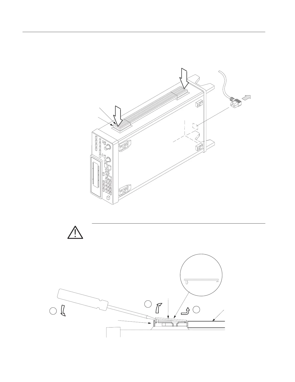
Power Cable
Cover
Block
Location of Slit
where flatĆbladed
screwdriver may be
inserted.
Location of Slit
where flatĆbladed
screwdriver may be
inserted.
Figure 1: Location of slit where flat-bladed screwdriver may be inserted
CAUTION. The latch of the cover can be released by lifting it up ward about 5
mm. Do not lift the cover more than necessary when releasing the latch. If so the
nail at the opposite side of the cover can be broken.
1
2
1
Cover
Block
Handle
Cross Section
of the Cover
Figure 2: Construction of the handle retainer (cross section)