Removal and Installation Procedures
AFG3000 Series Arbitrary/Function Generators Service Manual 6-15
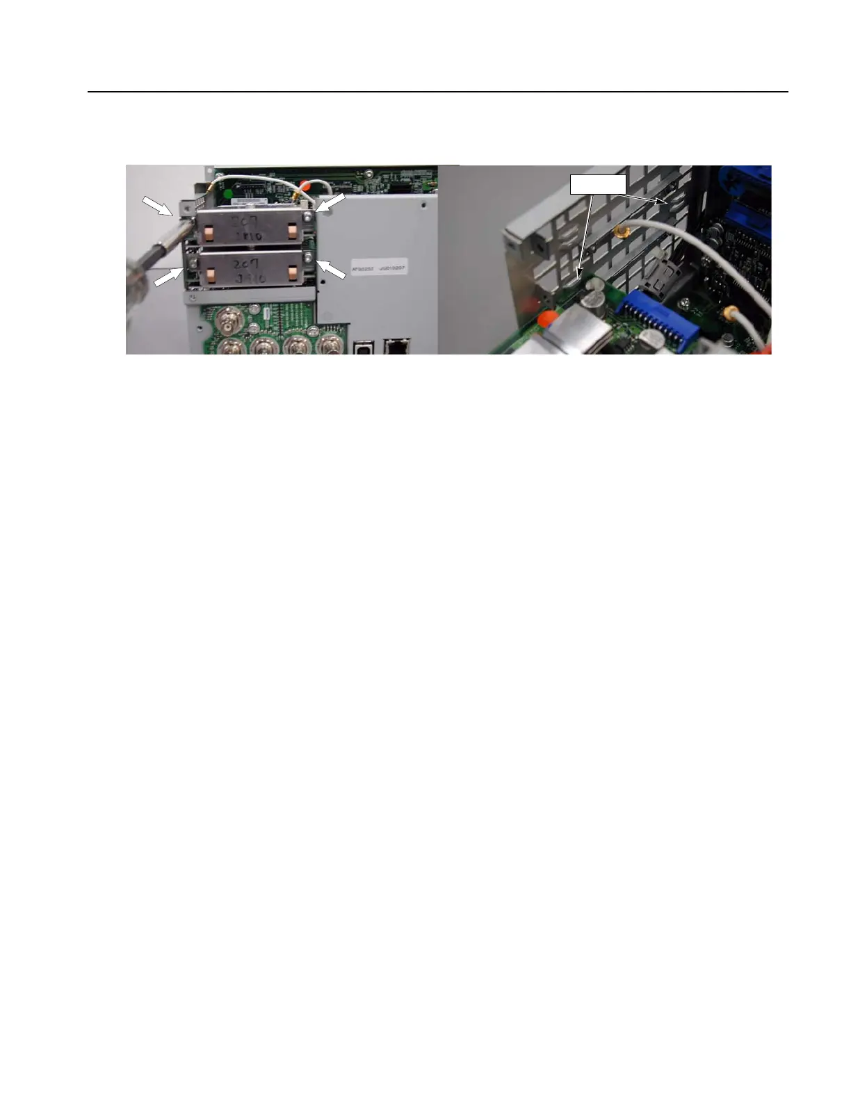
Figure 6-9: Output board removal
Installation. To install, reverse this procedure.
Separation of Rear Module and Main Chassis
To remove and replace the internal modules, Generator board, CPU board, Power
supply, fan, or backlight inverter board, you must first separate the rear module and
the main chassis. You will need a torque-limiting Torx T-15 screwdriver and a
flat-blade screwdriver for this procedure.
Removal. To separate the rear module and main chassis, refer to Figure 6-10 and
Figure 6-11 and follow these steps:
1. Disconnect the following cables:
The front-panel cable at J300
The display inverter cable from the LCD Display
The display data cable at J400 from the LCD Display
The add-in cable at J370 from the ADD Input connector
2. Remove the three screws attaching the CPU board to the main chassis.
3. Remove the two screws near the air outlet attaching the rear module and main
chassis.
Guide
 Loading...


