-1A
integrator to go
positive with respect
to
Vaz
(see Fig.
3-7).
then returns
it to
Vaz
potential, stopping only
when the
LD120 (U1601)
comparator changes
state. The count
is in
single clock
times.
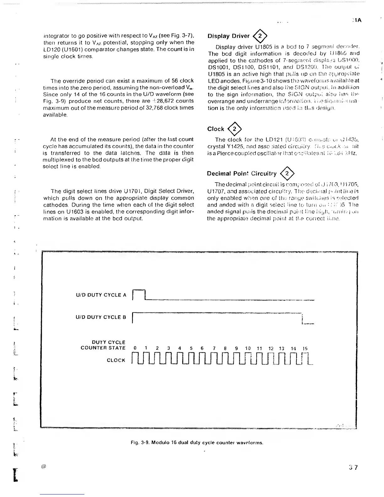
The
override period
can exist
a
maximum
of 56
clock
times into the zero
period, assuming
the
non-overload V,„.
Since
only
14
of the 16 counts
in
the
U/D
waveform (see
Fig.
3-9)
produce net
counts, there
are 4:28,672 counts
maximum
out
of the
measure period
of 32,768
clock times
available.
At the end
of the measure period
(after
the
last count
cycle
has accumulated its counts), the data in
the
counter
is
transferred to the data latches. The data is
then
multiplexed
to
t
tie
bed
outputs
at
the
time the proper
digit
select
line
is
enabled.
The
digit select lines drive U170I,
Digit Select Driver,
which pulls
down
on
the appropriate
display common
cathodes.
During the time when each
of
the
digit
select
lines
on U1603
is enabled, the
corresponding
digit
infor-
mation is available at
the
bed
output.
Display
Driver
Display
driver
U1805
is
a
bed to
7 segrnsn!
def:nder.
The bed
digit information
is decoded
by
tjI8f(5 and
applied to
the cathodes
of
7-segrnera
displa/s
USi'fOO,
DS1001,
DSIlOO, DS1101,
and DS12U0.
The output oi
U1805
is an active
high that
puiis
up
on
t.hn
approp, iate
LED
anodes.
Figure
3-10
shows the
waveforms
avail
aide
at
the
digit select lines and also
iiie SIGN
outpiii.
in addilion
to the
sign information, the
SiGN outpiii
also
iias ilK-
overrange and
underrange
iiiforinaiion. t
i
.e
sirpi n li- >!
ma
tion
is
the only information
used i.i
tins de.siyn.
Clock
The clock
for the LD121
(UiGOT.) cmi.v.st;
..J1435,
crystal
Y1425,
and assc .dated circuitry.
ri,;s cock
-tii tiit
is
a Pierce coupled
oscillator
.‘hat c'.c‘lintes
a I
1 i'. '..(.Li kHz.
Decimal
Point
Circuitry
Ttiedecimal point circuit
is
comi
osed ol
J
i /(G,
•
)
1
705,
U1707,
and
associated
circuhr/, TTic deciinai
p.
Tut line is
only enabled
w.'ion
one
of
the
range
switc.liei;
is
sc'lecterf
and anded with
a
digit select
line
tci turn
on
:
: 1:
)5
The
anded signal pmis
the
docintal point
line
liigfi,
(-rning
on
the
appropriate decimal point at
the
correct
ii.no.
f
 Loading...


