Theory
of
Operation
—
DM
501
A
Power
Supply
The 25 Vac
input to isolation transformer
T1301
is
supt)iiod
fiom
the
power module through rear interface
pins
13Annd 133. The output voltage
from pins7and9is
rectified by CR1422
and applied
to
U1325
and
U1335.
I
bese
throe-terminal
regulators provide the
I
15 V source
and
’2
V source.
The output voltage from T1301, pins 10
and
12,
is
rectified by CR1424 and CR1426
and applied
to
U1431.
This
Ihreo-termmal regulator provides the
f
5 V source.
All three-terminal regulators are internally current
limited.
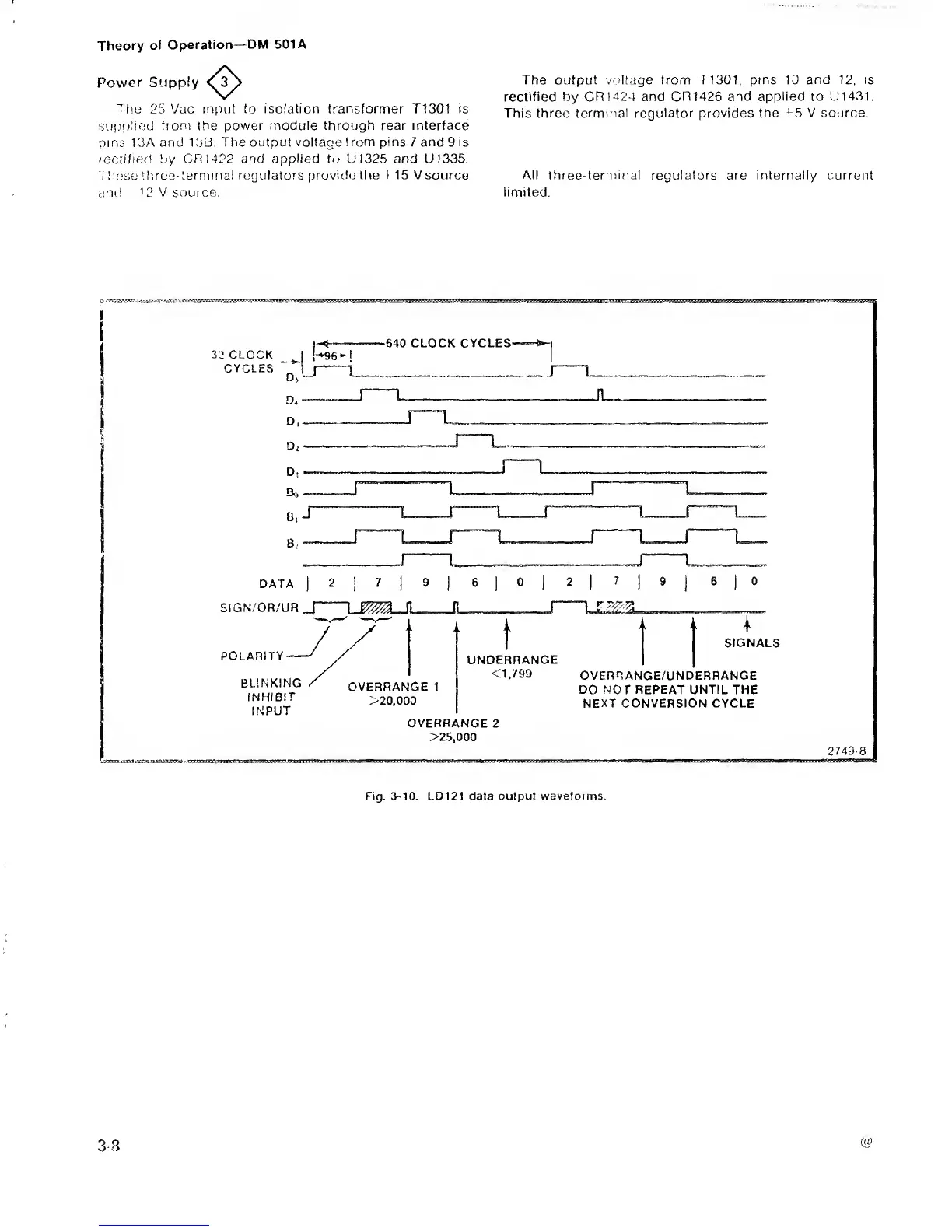
Fig.
3-10.
LDI21 data output
waveforms
 Loading...


