otv-iiu.i ‘i
i>M
501A
Introduction
This procedure checks the
electrical performance
requirements
as listed in the Specification
section in this
manual.
Perform the Adjustment procedure if the
instru-
ment fails to meet these checks. In some cases,
recalibra-
tion may not correct the discrepancy;
circuit trouble-
shooting is then indicated. Also, use
this
procedure to
determine acceptability of performance
in
an
incoming
inspection facility.
For
convenience,
many steps in this procedure check
the performance of this
instrument at only
one
value in
the
specified performance
range.
Any
value within the
specified range,
within appropriate limits,
may be sub-
stituted. Performance requirements
for
various tem-
perature
ranges are
listed in this procedure;
when
perfor-
ming the procedure, use
only
the
Display Limits listed
for
the ambient
temperature
in
which the instrument
is
operating.
Calibration Interval
To
ensure iristrumont accuracy,
check th.r
calibration
every 1000 hours of operation
oi
at a
n.i.iiuiUu.
cvei
y
six
months if used
infreq.ientiy.
Services Available
Tektronix, Ir.c. provides conipiote
in^.tim.ient rr>pair
and adjustment
at local fir>ld
se
vice
,i,a, ct She
factory
service
center.
Coiuaci
y
or local
i vl.u :
;
i;.;
,'ieid
office or representative fo; liirthe. inS , ct.on.
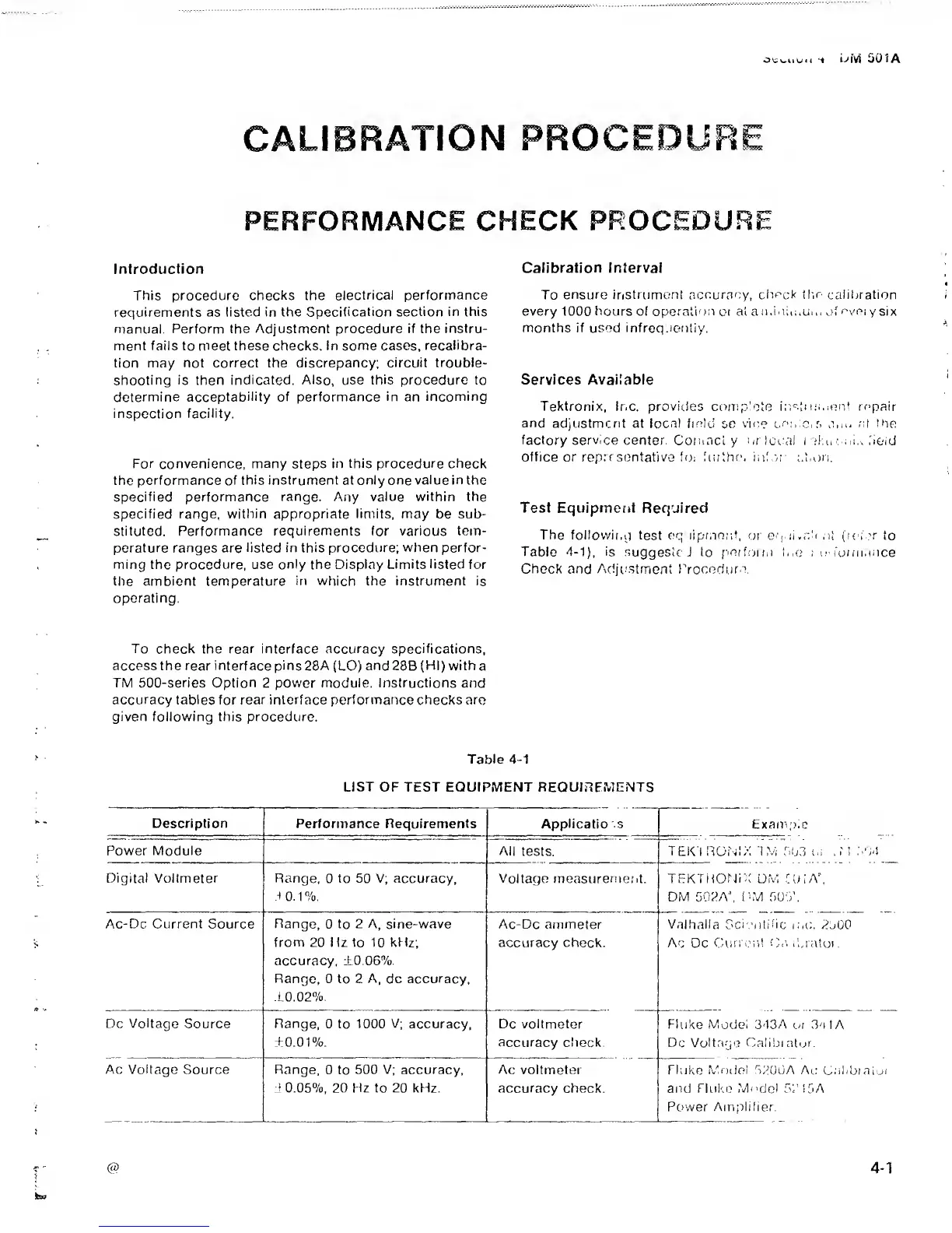
Test Equipment
Required
The following
test
equipi.nniit,
oi
er|,;i.,dt
,i! (let.’r
to
Table
4-1),
is
suggesic J to
ficrforiii
inc ; c: I'ormance
Chock and Adju.stment IVocedure.
To
check the rear interface accuracy specifications,
access the rear interface
pins
28A
(LO)
and28B
(Hi)
with
a
TM 500-series
Option
2
power
module.
Instructions
and
accuracy tables for rear interface performance checks are
given following this procedure.
Table
4-1
LIST
OF TEST EQUIPMENT REQUIPEMENTS
Description Performance
Requirements Appiicatio s
Exanv)ic
Power
Module
All
tests.
TEKTRONIX
'1
M 503 t.;
±1
h'±l
Digital Voltmeter Range,
0
to 50 V; accuracy,
s
0.1%.
Voltage measurernent. TEKTHONiX DM EdlA',
DM 502A',
IdM
505’.
Ac-Dc Current
Source
Range,
0 to
2 A, sine-wave
from 20 Hz to 10 kHz;
accuracy,
±0.06%.
Range, 0 to 2 A, dc accuracy,
LO.02%.
Ac-Dc ammeter
accuracy check.
Valhalla Sci 'nlidc
luc. 2500
Ac
Dc
Guri
i-’ii! OXvd.ratoi
.
Dc Voltage
Source Range, 0 to 1000
V;
accuracy,
±0.01%.
Dc voltmeter
accuracy
check
Fluke Mode; 343A
oi
3a
1
A
Dc Voltage Calibintor.
Ac
Voltage
Source Range,
0 to
500 V; accuracy,
J
0.05%,
20 Hz to 20 kHz.
i
Ac
voltmeter
accuracy check.
Fluke
Mfxioi
.5200A Ac Galibiaiui
and Flul'.e
Model
55'I5A
Power
Amplifier.
 Loading...


